Concrete pump

Active Publication Date: 2013-05-14
DRAGO JAMBRECINA
View PDF9 Cites 3 Cited by
  • Summary
  • Abstract
  • Description
  • Claims
  • Application Information

AI Technical Summary

Benefits of technology

This patent is about an improved concrete pumping system that solves common issues such as hardening concrete, limited cleaning speed, and difficulty maintaining and repairing equipment. The invention aims to provide a system that can pump out the contents of concrete delivered into the hoper, even if there is a delay in the delivery. It also ensures that the hoper is evenly shaped and can handle mixing concrete without risking it to set hard. Additionally, the invention provides easy access to inspect, maintain, or replace wearing parts and allows for measurement of the slump of concrete being delivered. Overall, the invention improves the efficiency and operability of concrete pumps.

Problems solved by technology

One issue known in the art of concrete pumps is that the equipment has to be cleaned quickly as concrete can set and harden in a short period of time.
Further, with more and more cars on the roads and obstacles encountered during concrete deliveries, these deliveries are often delayed and this limits the time a user has to work with the concrete before it starts to set.
Because of this, it is not possible to mix an entire volume of concrete either with a motorized Auger or tools like shovel which is desperately necessary during times when waiting for a concrete delivery truck.
If concrete were to set in the device, a user would be unable to resume pumping upon delivery of the next load and the entire pipe line could be lost, thus preventing the pump from operating and preventing the job from being completed.
In existing concrete pumps, inspection, maintenance or replacement of most wearing parts like, wear plate, wear ring and piston caps, piston's oil seals, swing tub, swing tub's bearing and seal are not easily accomplished because these parts are not easy accessible.
At present time no concrete pump known is fitted with such measuring devices, and there is not such a device available for retrofitting.

Method used


Image

  • Concrete pump
  • Concrete pump
  • Concrete pump

Examples


Embodiment Construction

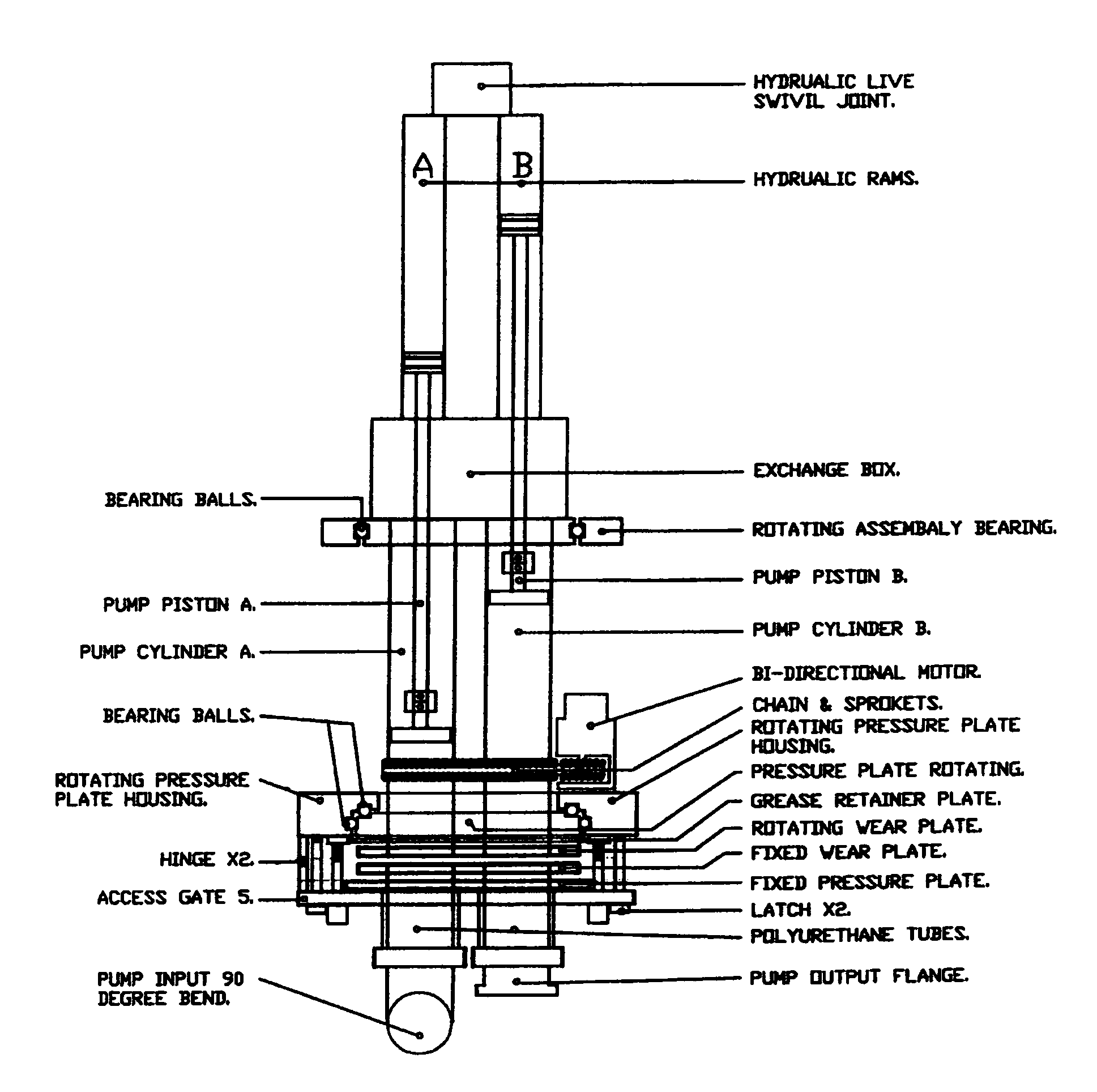
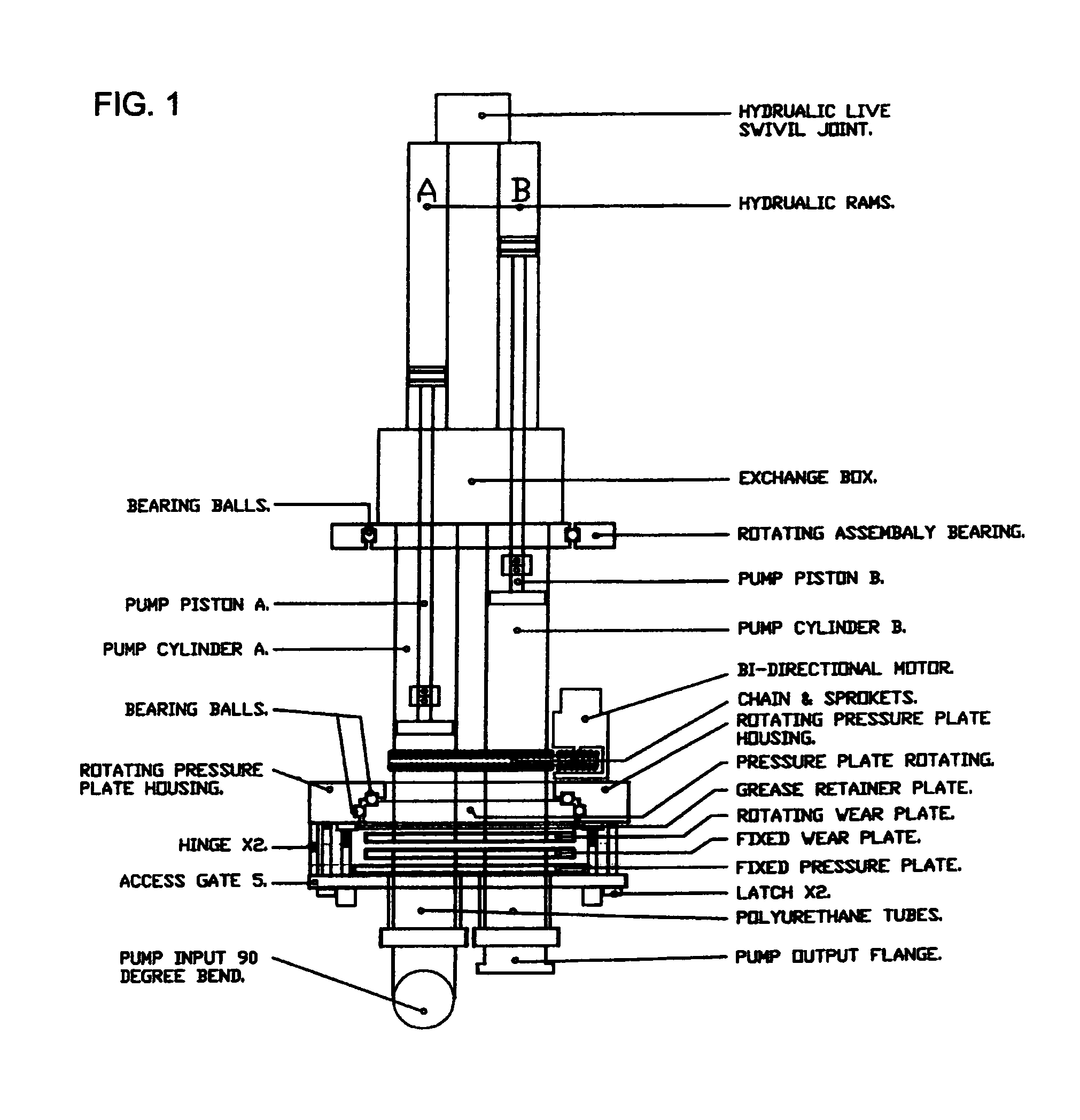
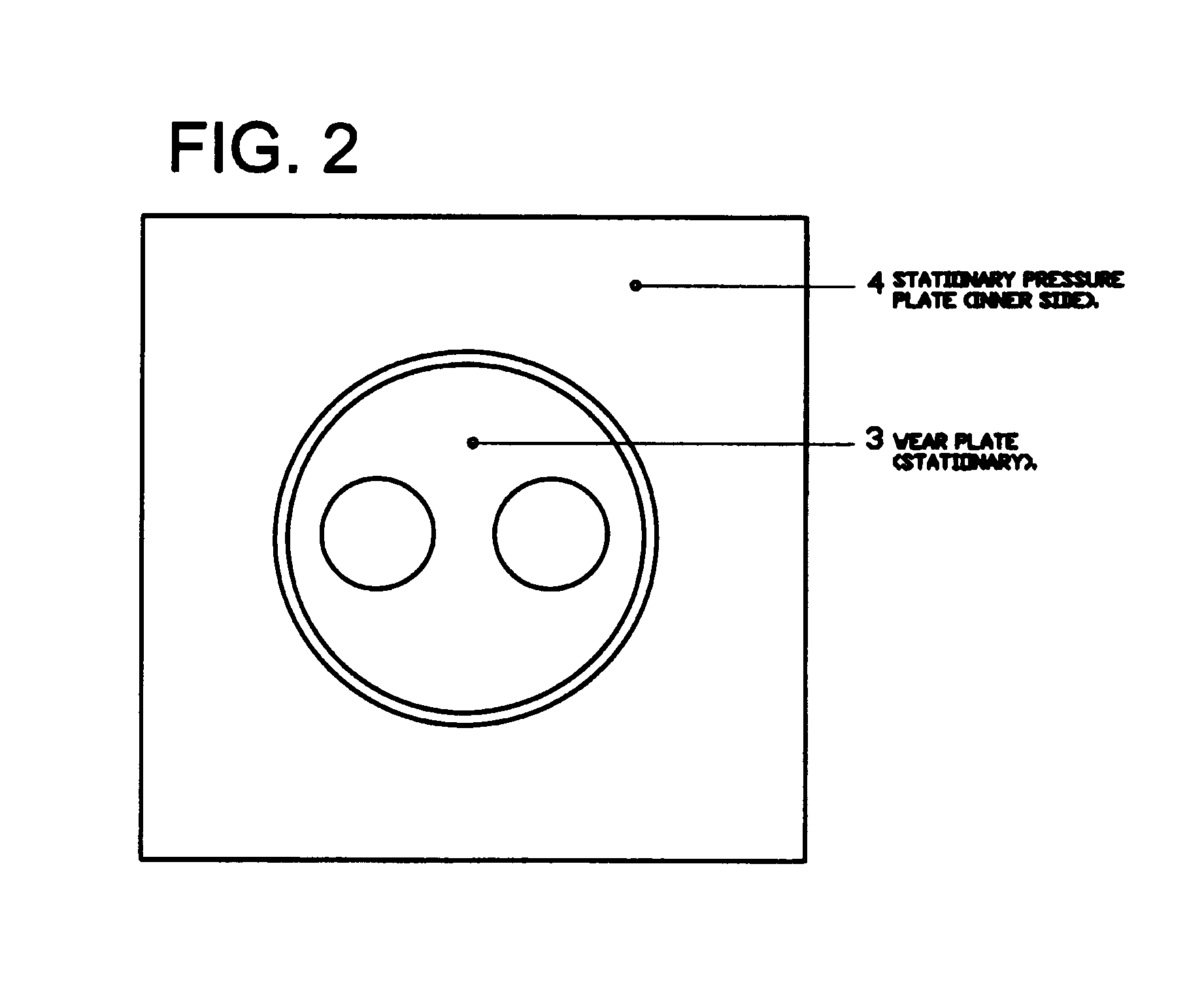
[0011]The pump of this invention has two rotating pumping cylinders, (cylinder a and cylinder b) a stationary assembly and a funnel like hoper 6. In this design, the pump cylinders are fastened to one side of a rotating pressure plate 1, the other side of the pressure plate is fastened to a rotating wear plate 2. While the other ends of the pump cylinders are fastened to an exchange box, together with a rotating assembly back bearing. The other side of the exchange box is hydraulic cylinders, and the hydraulic cylinders have a hydraulic dual swivel joint fastened thereto. The wear plate, the pressure plate, together with an exchange box and hydraulic cylinders rotate clock wise and anti-clock wise by 180 degrees. The rotating wear plate 2 is pressed and is sliding against a stationary wear plate 3. The stationary wear plate is fastened to a stationary pressure plate 4. The stationary pressure plate 4 is retained on an access gate 5. The stationary pressure plate has one hole (concre...


PUM


Abstract

A Concrete Pump is a mechanical device comprising of a round funnel shape hoper, pump outlet, rotating pressure and wear plates. Attached to the rotating pressure and wear plates are rotating pump cylinders and opposite the pump cylinders are a rotating wear plate. Pressed against the rotating wear plates is the stationary wear. A hoper outlet and a pump outlet flange are attached to the stationary wear plate. The pump functions as follows: concrete from the hoper passes through the stationary and rotating wear plates into one pump cylinder, at the same time, concrete from another cylinder (previously field with concrete) is pushed through the rotating wear plate and through the stationary wear plate into the pump's outlet. When the pistons reach the end of the cylinders the rotating wear plates and concrete cylinders rotate by 180 degrees and the process is repeated again. The pump is designed so that an entire volume of concrete or similar pumping substance is pumped out of the hoper.

Description

BACKGROUND AND SUMMARY OF THE INVENTION[0001]There are many different concrete pumping systems. The most common type is a two cylinder type Piston Pump. Amongst other components, they all have pump cylinders stationed and fastened to the outside back flat wall of the hoper, somewhat above the hoper's floor and aligned inside the hoper thru the same size opening on the hoper forming an alignment inside the hoper with the wear plate, wear ring and swing tube which is situated inside the hoper, thru which concrete is pumped into the pump's outlet, situated on front of pump's hoper. One issue known in the art of concrete pumps is that the equipment has to be cleaned quickly as concrete can set and harden in a short period of time. Further, with more and more cars on the roads and obstacles encountered during concrete deliveries, these deliveries are often delayed and this limits the time a user has to work with the concrete before it starts to set. The following invention is directed to...

Claims


Application Information

Patent Timeline
IPC IPC(8): F04B39/10
CPCF04B9/1172F04B53/22F04B15/023
Inventor DRAGO, JAMBRECINA
Owner DRAGO JAMBRECINA
Why Eureka
Try Eureka