Methods for controlling electrical devices using motion detection

a technology of motion detection and electrical devices, applied in the field of motion detection control of electrical devices, can solve the problems of more complex systems controlled using motion detection, scanning systems which are very complex and costly, and achieve the effect of reducing energy input and compensating for the fluctuations in the brightness of the surrounding

Active Publication Date: 2013-04-30
FIRST SENSOR MOBILITY GMBH
View PDF8 Cites 11 Cited by
  • Summary
  • Abstract
  • Description
  • Claims
  • Application Information

AI Technical Summary

Benefits of technology

[0016]The reduction of the energy consumption during continuous provision of readiness of the control device through a staggered method with identification, verification and exclusion criteria is supported by the subdivision of the monitoring area into a pre-detection and detection area. Events which are detected in the pre-detection area merely lead to a next step of identification and verification. Therefore, the readiness is provided, however the possibility of an exclusion of an event is even higher here. If the event however is detected already in the detection area the steps until the control is triggered are regularly reduced so that the criteria to exclude events become less important.
[0036]The temporal separation of distance measurement and motion detection allows further energy reductions of single function blocks, to only activate the one that is in use. Additionally, the photo diodes of the control device can be activated as solar cells and can serve the energy production for the period of time of the hibernating state in which the diodes are not used for the control method.

Problems solved by technology

However, more complex systems are controlled using motion detection, e.g. control of robots within automatic plants without colliding.
A three-dimensional object recognition, which also comprises information on the distance to the object, often takes place using stereoscopic cameras or scanning systems which however are very complex and costly.

Method used


Image

  • Methods for controlling electrical devices using motion detection
  • Methods for controlling electrical devices using motion detection
  • Methods for controlling electrical devices using motion detection

Examples


Embodiment Construction

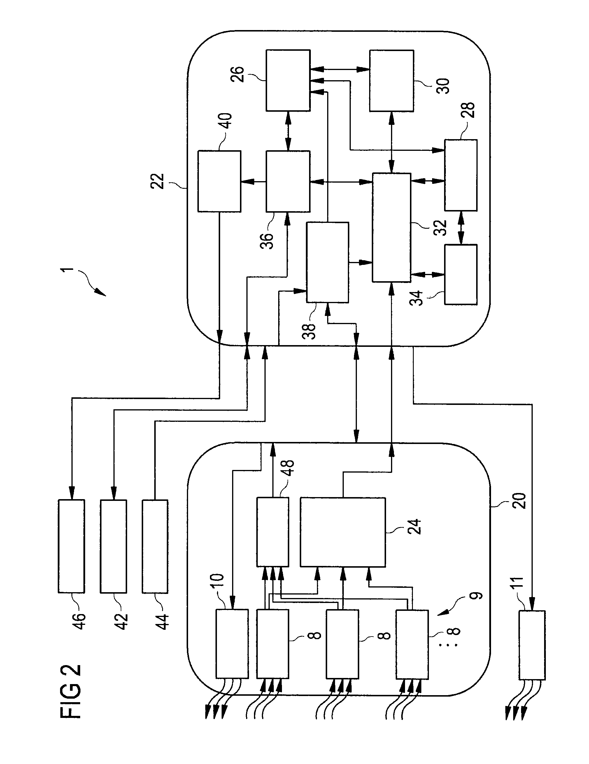
[0049]The realization of the in the following described method of control is based on a housed sensor chip 1 according to FIG. 1.

[0050]FIG. 1 shows an embodiment of a sensor chip 1 according to the invention within its package 2. Package 2 can generally be understood as the chip's direct housing which often is consists of a grouting compound that meets the electrical and mechanical requirements whose material is attuned to the expected chemical and thermal strain. The package 2 in this embodiment is generally defined as QFP-housing (Quas Flat Package-housing) shaped as a flat rectangle whose electrical connectors 6, generally designated as pins, are arranged at the side edges. With such a shape and realization of connectors, the sensor chip 1 can be integrated into different systems through a suitable housing.

[0051]The package 2 is made opaque with a transparent cap 4 above the optical detector, a in the following described arrangement of photodiodes, and the optical emitter 10. The...


PUM


Abstract

A method and device to control electrical devices using motion detection are presented, through which an object inside a monitoring area which is subdivided into a pre-detection area and a detection area is successively identified as well as verified in the detection area for reducing power input in standby mode and during operation in the main cycle using distance measurements and its position consequently determined. During the course of the distance measurements, the control device is brought into a readiness state and later on into operating state. After finishing the distance measurements and determining the position of the object in the detection area, an output signal which serves to control an external electrical device is generated by a control device.

Description

CROSS REFERENCE TO RELATED APPLICATIONS[0001]This application claims priority of German application No. 10 2009 050 574.1 filed on Oct. 23, 2009, the entire disclosure of which is hereby incorporated herein by reference.[0002]The invention generally refers to a control of electrical devices on the basis of a three-dimensional motion detection of objects in a monitoring area. It refers in particular to a for this purpose used control device using a suitable motion detector which provides information on distances and local resolution as well as a method for controlling external electrical devices using such a control device.BACKGROUND OF THE INVENTION[0003]It is known that the presence of people in a specific detection area inside a room can be detected by means of various motion detectors with electro-magnetic radiation and sound waves, and to control a connected external electrical device by means of the detection. Generally in this case, the switching on lighting or cameras is know...

Claims


Application Information

Patent Timeline
Patent Type & Authority Patents(United States)
IPC IPC(8): G06F1/32G01S17/04G01S17/10G01S17/894
CPCG01S17/026G01S17/89G01S7/4813G01S17/10G01S17/04G01S17/894
Inventor BUSSE, ERIKVON HESSEN, WILHELM PRINZ
Owner FIRST SENSOR MOBILITY GMBH
Why Eureka
Try Eureka