
Radiation image detector

a detector and radiation image technology, applied in the field of radiation image detectors, can solve the problems of unnecessarily eliminating noise components, insufficient elimination of noise components, and susceptible output of electrical components, and achieve the effect of eliminating noise components and surely eliminating noise components

Active Publication Date: 2013-04-30
FUJIFILM CORP
View PDF9 Cites 5 Cited by
  • Summary
  • Abstract
  • Description
  • Claims
  • Application Information

AI Technical Summary

Benefits of technology

[0011]In view of the above, an object of the present invention is to provide a radiation image detector capable of surely eliminating noise components from a signal of a radiation image.
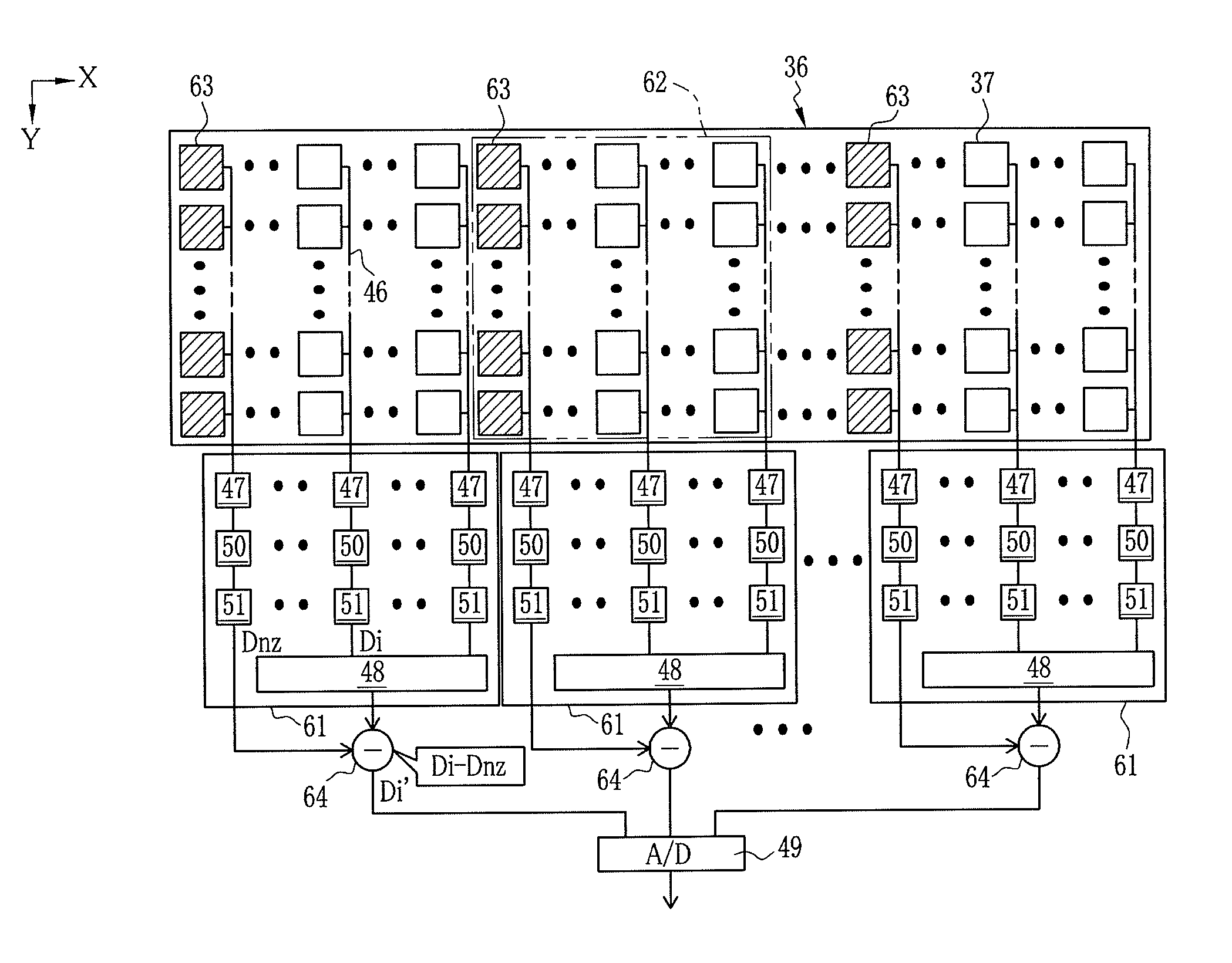
[0018]According to the present invention, plural rows of the pixels are made into one group, and the noise detecting elements are provided for each of the groups. Since subtraction is performed between the electric signal of the pixels and the electric signal of the noise detecting element in the same group, it is possible to perform elimination of noise components suitable for each of the groups. Accordingly, it is possible to surely eliminate the noise components from the signal of the radiation image.

Problems solved by technology

Generally speaking, output of an electrical component is susceptible to noise caused by an internal factor of the electrical component itself or an external factor such as an ambient environment.
When the subject or radiographer happens to bump into the X-ray image detector and the X-ray image detector is applied with impact, the X-ray image detector vibrates in response to the impact, and the vibration of the X-ray image detector causes noise.
When the noise is applied to a signal of image data, the noise causes a false image on the X-ray image, and the false image may lead to diagnosis error.
Further, the ASIC itself is a generation source of the noise.
Since the introduction of the noise varies in accordance with the group corresponding to each of the ASICs as described above, even if the output signal of the dummy pixels is uniformly subtracted from the output signal of the effective pixels as disclosed in Japanese Patent Laid-Open Publication No. 2009-081443, it is not possible to eliminate the noise components sufficiently, or image components which are not the noise components are unnecessarily eliminated.
Moreover, according to the method disclosed in Japanese Patent Laid-Open Publication No. 2009-128186, although it is possible to eliminate the noise components generated by the fluctuation of bias voltage, it is impossible to eliminate the noise components generated by the ASICs themselves.

Method used


Image

  • Radiation image detector
  • Radiation image detector
  • Radiation image detector

Examples


Embodiment Construction

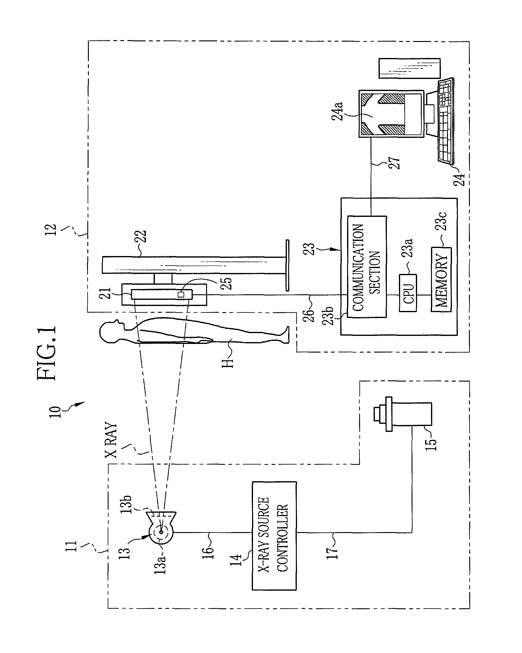
[0024]In FIG. 1, an X-ray imaging system 10 includes an X-ray generator 11 and an X-ray imaging device 12. The X-ray generator 11 consists of an X-ray source 13, an X-ray source controller 14 for controlling operation of the X-ray source 13, and an irradiation switch 15. The X-ray source 13 has an X-ray tube 13a for emitting X-rays and a collimator 13b for limiting an irradiation field of the X-rays emitted from the X-ray tube 13a.

[0025]The X-ray tube 13a has a cathode and an anode. The cathode is composed of a filament for emitting thermal electrons. The thermal electrons emitted from the cathode collide against the anode (target) to generate the X-rays. The target is in the shape of a circular disc. The target is a rotating anode which rotates such that a focal spot thereof moves along a circumferential orbit. Thereby, it is possible to prevent elevation in temperature of the focal spot against which the thermal electrons collide. The collimator 13b is composed of a plurality of ...


PUM


Abstract

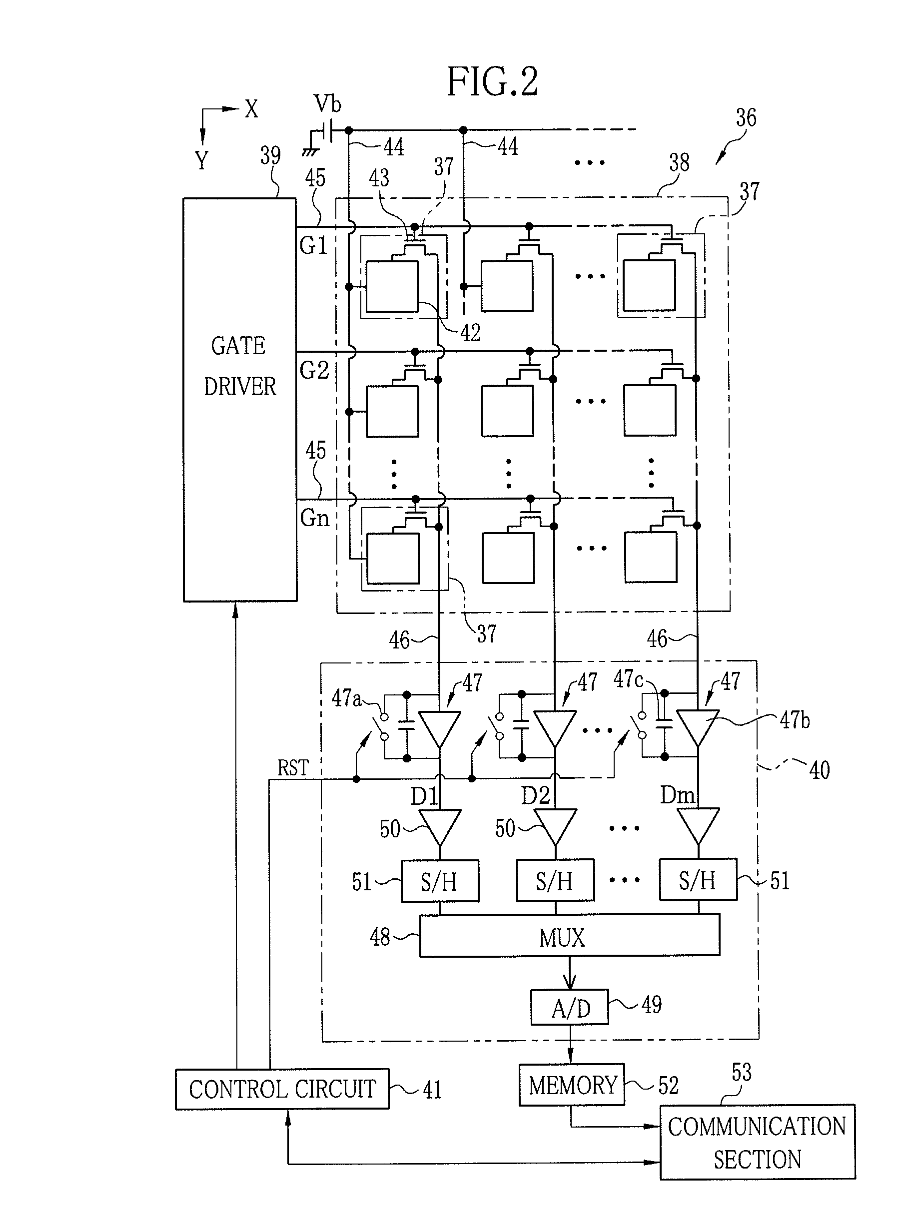
A FPD includes a signal processing circuit and noise detecting elements provided for each group containing plural columns of pixels. The signal processing circuit converts signal charges accumulated in the pixels into electric signals and outputs the electric signals. Each of the noise detecting elements has the same structure as that of the pixel, but does not have a function of accumulating the electric charges. A voltage signal of the noise detecting element represents noise components. A subtractor subtracts the voltage signal of the noise detecting elements from a voltage signal of the pixels which is outputted from the noise processing circuit.

Description

BACKGROUND OF THE INVENTION[0001]1. Field of the Invention[0002]The present invention relates to a radiation image detector for detecting a radiation image.[0003]2. Description of the Related Art[0004]A radiation imaging system such as X-ray imaging system is constituted of an X-ray generator for generating X-rays and an X-ray imaging device for capturing an X-ray image of a subject. The X-ray generator has an X-ray source for irradiating X-rays toward a subject, an X-ray source controller for controlling operation of the X-ray source, and an irradiation switch for entering a command for starting irradiation of X-rays. The X-ray imaging device has an X-ray image detector for detecting an X-ray image in response to the X-rays having transmitted through the subject, and an imaging controller for controlling operation of the X-ray image detector.[0005]An X-ray image detector provided with a flat panel detector (FPD) instead of an X-ray film or an imaging plate (IP) as a detector has be...

Claims


Application Information

Patent Timeline
Patent Type & Authority Patents(United States)
IPC IPC(8): G01T1/24
CPCG01T1/247H04N5/32H04N5/357H04N5/374G01T1/2018H04N25/60H04N25/76G01T1/20184
Inventor KONDOU, KIYOSHI
Owner FUJIFILM CORP
Learn More