
Three-dimensional display, fabricating method and controlling method thereof

a three-dimensional display and control method technology, applied in the field of display, can solve the problems of affecting display quality, affecting the resolution of the three-dimensional images seen by the viewer wearing polarized glasses, and flicker phenomenon of the display image, so as to prevent flicker phenomenon and maintain the resolution of the three-dimensional image

Active Publication Date: 2013-04-23
AU OPTRONICS CORP
View PDF13 Cites 2 Cited by
  • Summary
  • Abstract
  • Description
  • Claims
  • Application Information

AI Technical Summary

Benefits of technology

The present invention provides a three-dimensional display that can show three-dimensional images with high resolution and prevent flickering. The display panel has a liquid crystal phase modulator that controls the phase retardation of the images, allowing the viewer to see individual images through glasses with polarized directions perpendicular to each other. The display also includes a quarter-wave plate, a half-wave plate, or a combination thereof to increase the viewing angle and improve the display quality of images.

Problems solved by technology

However, the time-multiplexed type usually causes flicker phenomenon to the display images.
Although the use of the spatial-multiplexed type may prevent the flicker phenomenon, the resolution of the three-dimensional images seen by the viewer wearing polarized glasses is 50% reduced, which affects the display quality.

Method used


Image

  • Three-dimensional display, fabricating method and controlling method thereof
  • Three-dimensional display, fabricating method and controlling method thereof
  • Three-dimensional display, fabricating method and controlling method thereof

Examples


Embodiment Construction

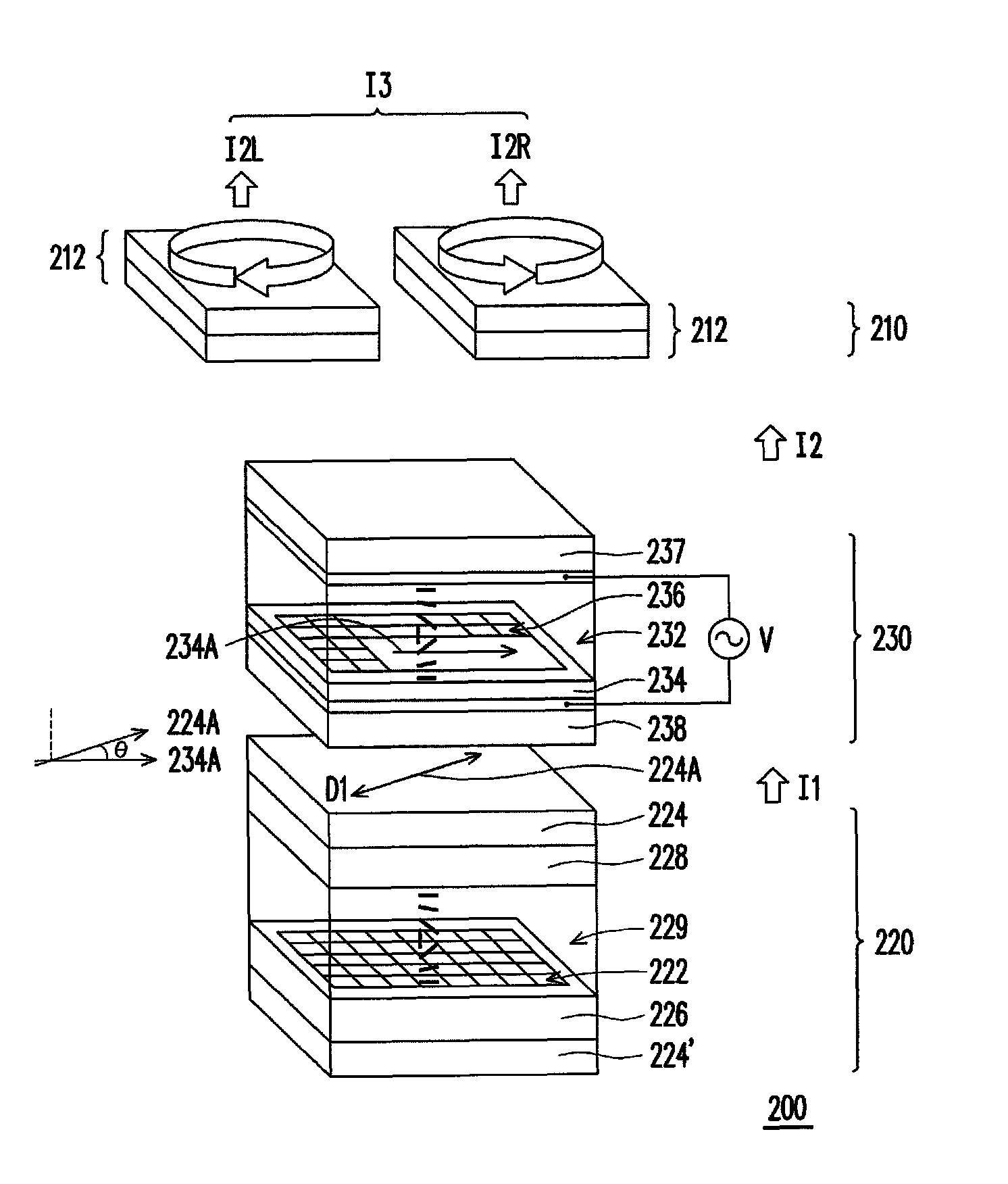
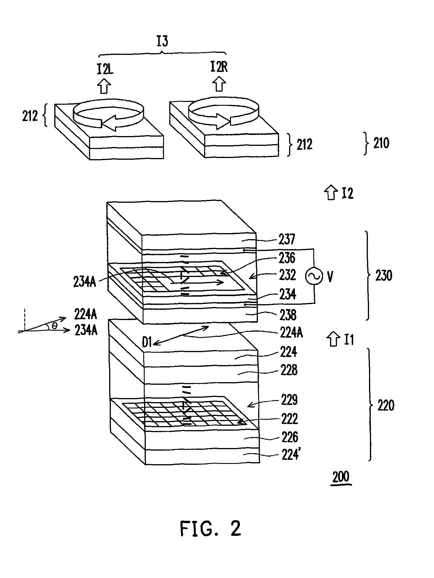
[0026]FIG. 2 is a schematic view illustrating a three-dimensional display according to an embodiment of the present invention. Referring to FIG. 2, a three-dimensional display 200 is adapted for a viewer to watch through glasses 210, wherein the glasses 210 comprise two lenses 212 having polarized directions perpendicular to each other, so as to form two polarized lights having polarized directions perpendicular to each other after a light passes through the lenses 212. For instance, the glasses 210 may comprise two circular polarized lenses 212 having different polarized directions. Light is converted into a levorotary polarized light and a dextrorotary polarized light after passing through the lenses 212. Moreover, the three-dimensional display 200 comprises a display panel 220 and a liquid crystal phase modulator 230. The display panel 220 has a plurality of pixels 222 arranged in array and a polarizer 224, wherein each of the pixels 222 comprises at least a signal line (not show...


PUM


Abstract

A three-dimensional display for the viewer to watch through glasses is provided, wherein the glasses have two lenses and the polarized directions thereof are perpendicular to each other. The three-dimensional display includes a display panel and a liquid crystal phase modulator. The display panel, suitable for displaying an image, has a plurality of pixels arranged in array and a polarizer having a transmission axis, wherein the polarizer disposed between the pixels and the glasses. The liquid crystal phase modulator suitable for providing phase retardation includes a liquid crystal layer and an alignment layer adjacent to the display panel. An included angle between an alignment direction of the alignment layer and the transmission axis is substantially equal to n×45 degrees, wherein an absolute value of n is an integer. The liquid crystal phase modulator adjusts a phase of the image and then outputs an image with three-dimensional information.

Description

CROSS-REFERENCE TO RELATED APPLICATION[0001]This application claims the priority benefit of Taiwan application serial no. 97134206, filed on Sep. 5, 2008. The entirety of the above-mentioned patent application is hereby incorporated by reference herein and made a part of this specification.BACKGROUND OF THE INVENTION[0002]1. Field of the Invention[0003]The present invention relates to a display, a fabricating method, and a controlling method thereof, and particularly relates to a three-dimensional display suitable for providing corresponding phase retardation to a display panel, a fabricating method, and a controlling method thereof.[0004]2. Description of Related Art[0005]As technology advances and develops, people's eagerness for better material life and spiritual life are increasing without a pause. When it comes to the spiritual life, in the world of technology, most people have the desire to realize their imagination and to experience it vividly with the help of various display...

Claims


Application Information

Patent Timeline
Patent Type & Authority Patents(United States)
IPC IPC(8): H04N15/00H04N13/04H04N13/02H04N13/337
CPCG02B27/26H04N13/0434H04N13/0497H04N13/337H04N13/398H04N13/30G02B30/25
Inventor CHEN, CHAO-YUANCHEN, CHIH-WENLIU, GENG-YULU, WAN-HUACHANG, TING-JUI
Owner AU OPTRONICS CORP
Learn More