
Vehicle control device

a technology for controlling devices and vehicles, applied in the direction of brake systems, instruments, transportation and packaging, etc., can solve the problems of limited movement of vehicles, inconvenience, and unknown problems, and achieve the effect of reducing the number of vehicles

Active Publication Date: 2013-04-16
TOYOTA JIDOSHA KK
View PDF24 Cites 16 Cited by
  • Summary
  • Abstract
  • Description
  • Claims
  • Application Information

AI Technical Summary

Benefits of technology

The vehicle control device described in this patent allows for the detection and prevention of abnormal shifting in a vehicle's shift position detection system. This is achieved by an abnormality detecting means that can detect abnormalities in the shift position detection means, such as an abnormality in the actuator or the shift operating device. The device also includes a shift-operation determining means that can determine if the shift operating device is shift-operated by the driver or not, based on a detection signal from the other detection means that is not abnormal. This allows for the release of the vehicle movement prevention based on the driver's intention, even if an abnormality is detected in the shift position detection system. The device can also release the vehicle movement prevention if a predetermined time has elapsed from the driver's shift operation. Overall, this device improves the accuracy and reliability of shifting in vehicles with shift-by-wire control systems.

Problems solved by technology

However, though a parking lock is effected by the parking lock mechanism when the fail-safe processing is executed to switch the driving range to P range, Patent Document 1 does not refer to a means for releasing the parking lock of a vehicle having an abnormality in the control system.
Therefore, the controller described in Patent Document 1 may experience an inconvenience that movement of the vehicle is limited due to the unreleased parking lock when the parking lock is applied to the vehicle having an abnormality in the control system.
This problem is still unknown.

Method used


Image

  • Vehicle control device
  • Vehicle control device
  • Vehicle control device

Examples


first embodiment

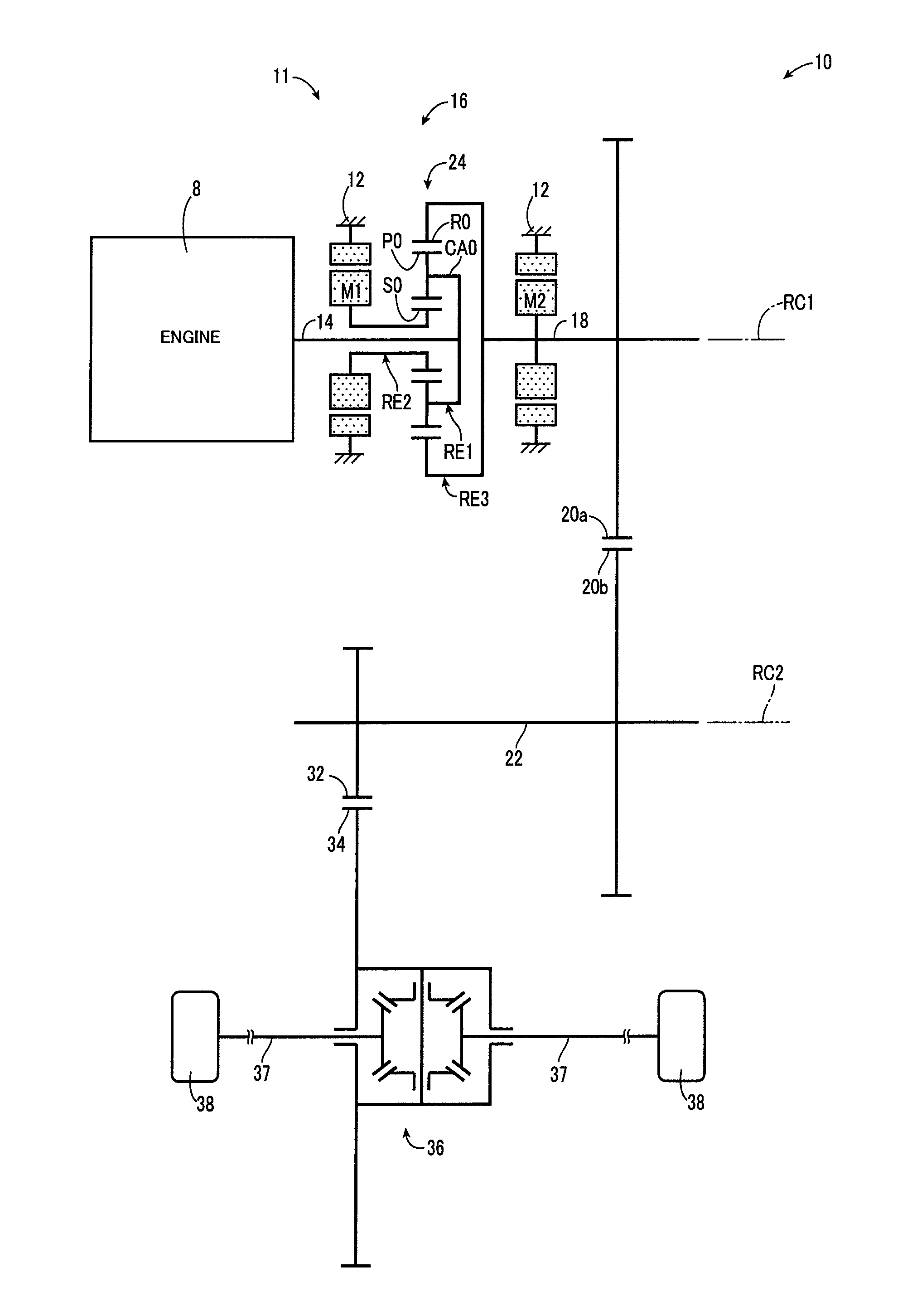
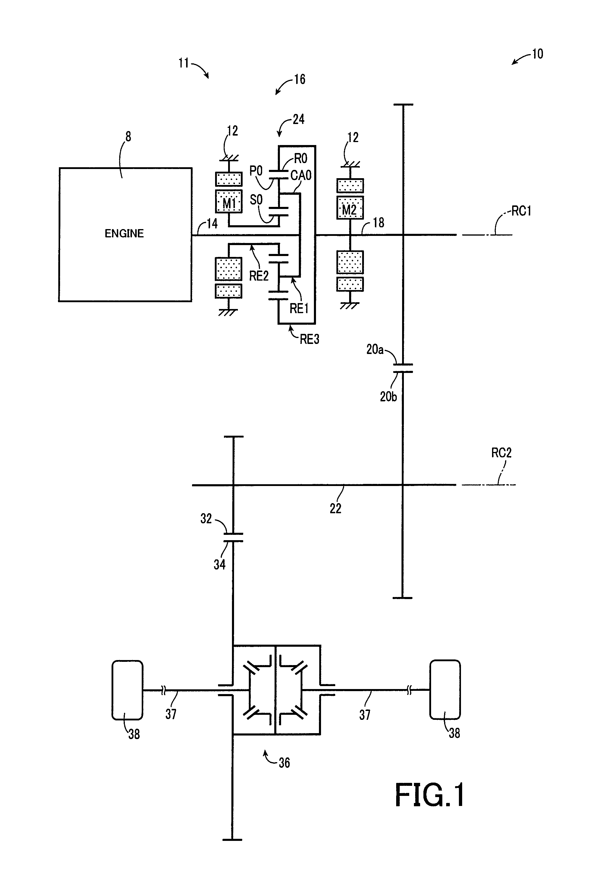
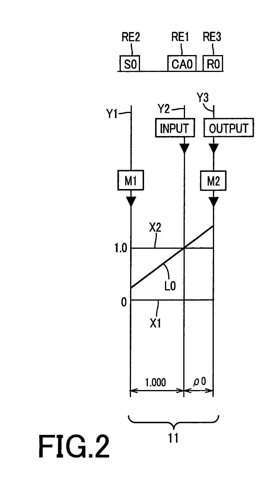
[0041]FIG. 1 is a diagrammatic view for explaining a power transmission device for vehicle 10 (hereinafter, represented as “power transmission device 10”) to which a control device of the present invention is applied. Although a vehicle to which the control device of the present invention is applied may be any type of vehicle such as a normal engine vehicle, a hybrid vehicle, and an electric-powered vehicle, following description is given of an example where the control device of the present invention is applied to the power transmission device 10 advantageously used in the hybrid vehicle. Referring to FIG. 1, the power transmission device 10 includes, sequentially arranged on a first axis RC1 within a transmission case 12 (hereinafter, represented as “case 12”) in the form of a non-rotating member fitted to a vehicle body, an input shaft 14 serving as an input rotary member; a differential portion 11 serving as a continuously variable transmission portion coupled directly or indire...

second embodiment

[0110]A function block diagram of a second embodiment is similar to the function block diagram of FIG. 9 of the first embodiment. In the second embodiment, the shift-operation determining means 114 is replaced by a shift-operation determining means 124, with the other means being common to the two embodiments. Differences therebetween will chiefly be described hereinbelow.

[0111]Referring again to FIG. 9, similar to the shift-operation determining means 114, the shift-operation determining means 124 determines based on a detection signal from at least one of the shift sensor 46 and the select sensor 48 whether the shift operating device 42 is shift-operated by the driver or not. The shift-operation determining means 124 is similar to the shift-operation determining means 114 of the first embodiment in that it makes the determination also when one of the shift sensor 46 and the select sensor 48 is abnormal and that, in such a case, the determination is made based on a detection signal...

third embodiment

[0115]A function block diagram of a third embodiment is similar to the function block diagram of FIG. 9 of the first embodiment. In the third embodiment, the abnormality detecting means 110 of the first embodiment is replaced by an abnormality detecting means 130; the vehicle movement prevention control means 118 of the first embodiment is replaced by a vehicle movement prevention control means 132; and the shift position determining means 120 of the first embodiment is replaced by a shift position determining means 134, with the other means being common to the two embodiments. Differences therebetween will chiefly be described hereinbelow.

[0116]The abnormality detecting means 130 of FIG. 9 has, in addition to the function of the abnormality detecting means 110 of the first embodiment, a function of determining, when the shift position detection means (the shift sensor 46 and / or the select sensor 48) having an abnormality detected recovers the normality, that the shift position dete...


PUM


Abstract

A vehicle control device includes: an abnormality detecting portion that detects an abnormality in at least part of a shift position detection portion detecting a shift position; a shift-operatoin determining portion that determines, based on a detection signal from the shift position detection portion, whether a shift operating device is shift-operated or not by a driver, and a vehicle movement prevention control portion that, in a case where a movement of a vehicle is prevented by an actuator and in a case where the abnormality in part of the shift position detection portion is detected by the abnormality detecting portion, permits the actuator to release the prevention of the movement of the vehicle if it is determined by the shift-operation determining portion that the shift operating device is shift-operated by the driver.

Description

TECHNICAL FIELD[0001]The present invention relates to a shift-by-wire technology for a vehicle.BACKGROUND ART[0002]A vehicle control device employing a so-called shift-by-wire (SBW) has hitherto been known in an automatic transmission for a vehicle. The vehicle control device detects a shift position of a shift operating device by a sensor included in the shift operating device to determine a shift range corresponding to the shift position detected. Corresponding to the shift range determined, the vehicle control device then outputs a control signal to the automatic transmission, etc. Specifically, if the shift range determined based on a detection signal from the sensor is a driving range, then the vehicle control device outputs a control signal for gear change corresponding to the driving range to the automatic transmission to thereby execute a gear change of the automatic transmission, whereas if the determined shift range is a parking range (P range), then it outputs a control s...

Claims


Application Information

Patent Timeline
Patent Type & Authority Patents(United States)
IPC IPC(8): G01M17/00B60K6/445B60K20/02B60T1/06B60W10/10B60W20/00F16H59/08F16H63/34F16H63/50
CPCB60K6/445B60T1/005B60T1/10F16H61/12F16H63/483F16H63/3491Y10T477/60F16H2061/1208Y02T10/6239F16H2061/1284Y02T10/62
Inventor TSUTSUMI, TAKAHIKOINOUE, TAKASHIKITAORI, ICHIROKAWAGUCHI, KAZUOYUMA, TAKASHI
Owner TOYOTA JIDOSHA KK
Learn More