
Metal wood club with improved moment of inertia

a technology of inertia and metal wood, which is applied in the field of improved metal wood or driver golf clubs, can solve the problems of lack of suitable drive or metal wood clubs, substantially square shape of driver clubs, and environmental effects that are beyond the control of golf equipment designers, and achieves the effects of improving the rotational moment of inertia and the location of the center of gravity

Active Publication Date: 2013-04-16
ACUSHNET CO
View PDF67 Cites 68 Cited by
  • Summary
  • Abstract
  • Description
  • Claims
  • Application Information

AI Technical Summary

Benefits of technology

This approach enhances forgiveness on off-center hits by increasing the club head's resistance to twisting, allowing for more accurate and farther shots without exceeding USGA limits, particularly benefiting mid to high handicap players.

Problems solved by technology

Thus, a major challenge is to design the club face and club body to resist permanent deformation or failure by material yield or fracture.
However, these environmental effects are beyond the control of the golf equipment designers.
However, the '586 application limits the shape of the driver club to be substantially square when viewed from the top, and the moment of inertia in the horizontal direction through the center of gravity is significantly lower than the moment of inertia in the vertical direction.
However, most oversize drivers on the market at this time have moments of inertia in the range of about 4,000 to 4,300 g·cm2.
Moreover, the current art lacks a suitable drive or metal wood club that has a large moment of inertia around the vertical axis Iyy or a large moment of inertia around the horizontal axis Ixx both through the center of gravity when compared to the volume of the club head.

Method used


Image

  • Metal wood club with improved moment of inertia
  • Metal wood club with improved moment of inertia
  • Metal wood club with improved moment of inertia

Examples


Embodiment Construction

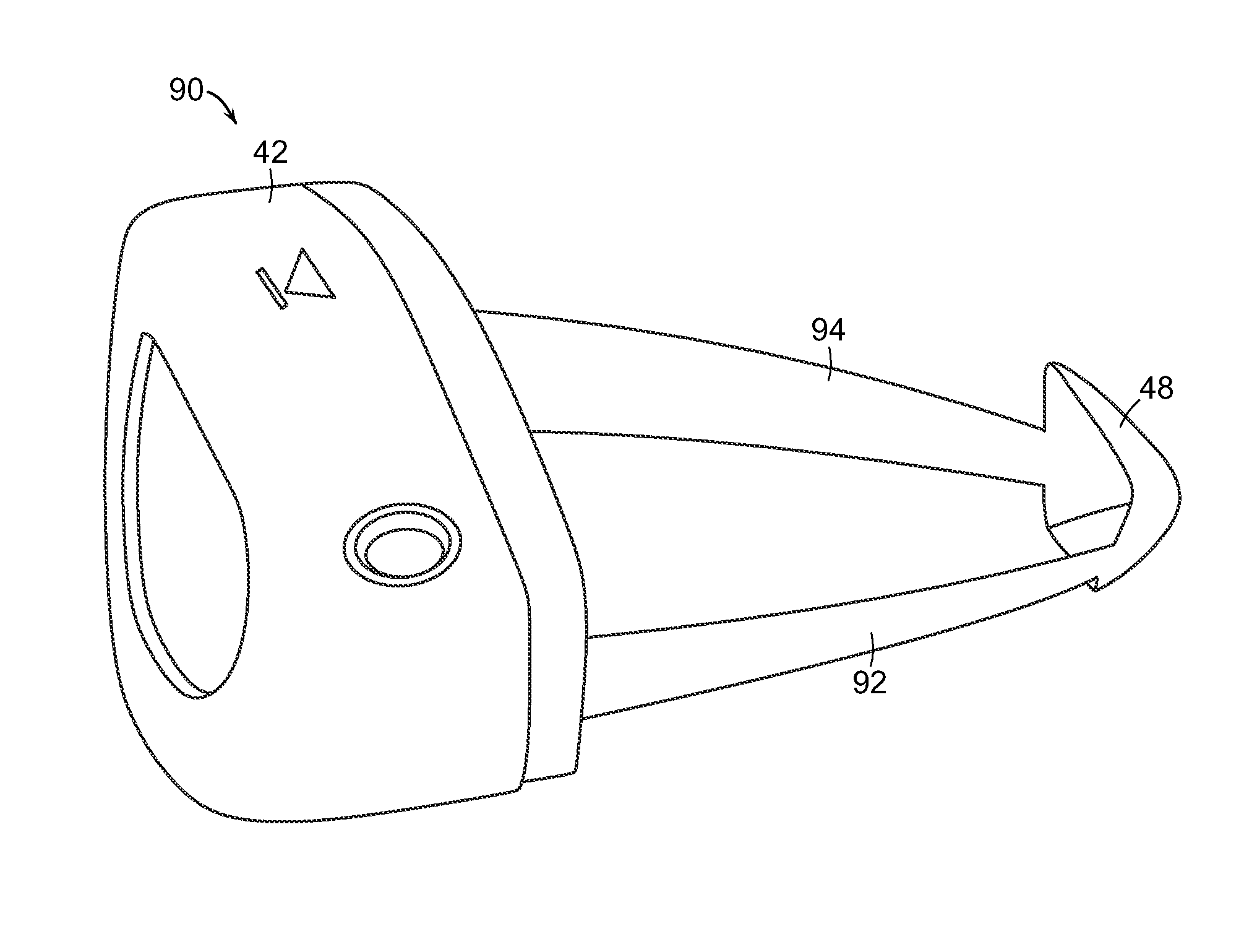
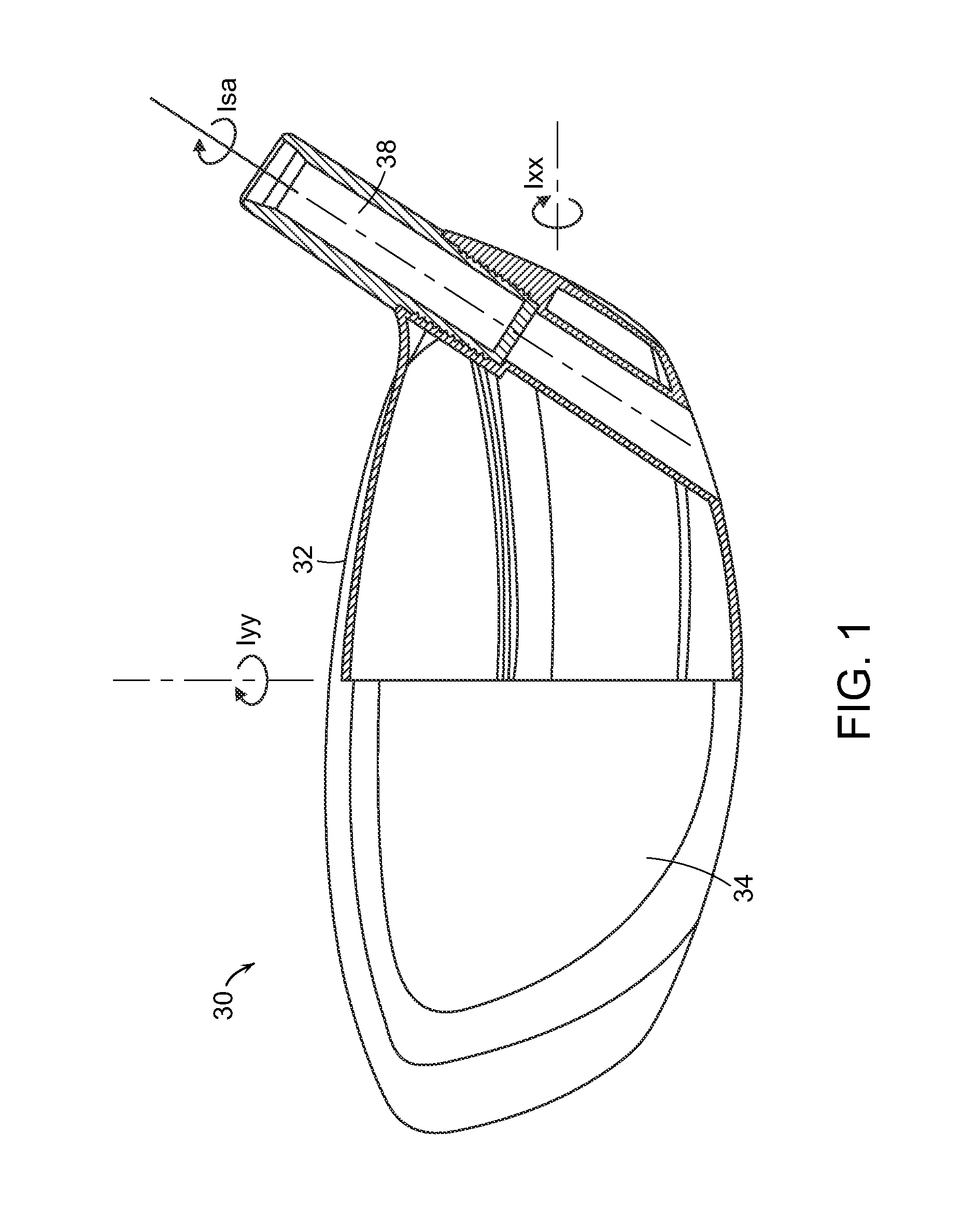
[0026]Rotational moment of inertia (“MOI” or “Inertia”) in golf clubs is well known in the art, and is fully discussed in many references, including U.S. Pat. No. 4,420,156, which is incorporated herein by reference in its entirety. When the inertia is too low, the club head tends to rotate excessively from off-center hits. Higher inertia indicates higher rotational mass and less rotation from off-center hits, thereby allowing off-center hits to fly farther and closer to the intended path. Inertia can be measured about a vertical axis going through the center of gravity of the club head (Iyy), and about a horizontal axis through the center of gravity (c.g.) of the club head (Ixx), as shown in FIG. 1. The tendency of the club head to rotate around the vertical y-axis through the c.g. indicates the amount of rotation that an off-center hit away from the y-axis causes. Similarly, the tendency of the club head to rotate around the horizontal x-axis through the c.g. indicates the amount ...


PUM


Abstract

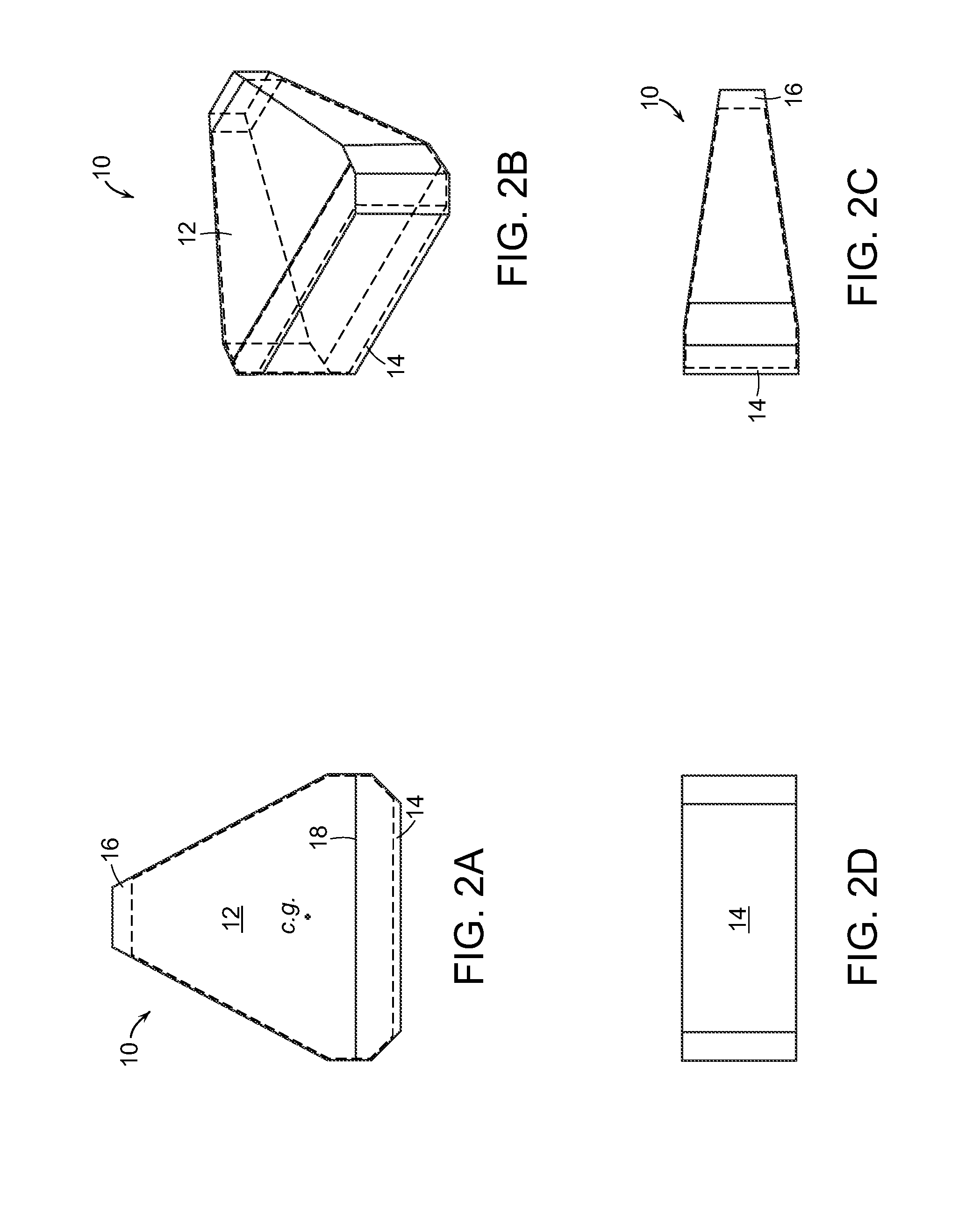
A more efficient triangular shape for metal wood clubs or driver clubs is disclosed. This triangular shape allows the clubs to have higher rotational moments of inertia in both the vertical and horizontal directions, and a lower center of gravity.

Description

CROSS-REFERENCE TO RELATED APPLICATION[0001]The present application is a continuation of U.S. patent application Ser. No. 12 / 340,925, filed Dec. 22, 2008, now U.S. Pat. No. 7,931,546 which is a Continuation-In-Part of U.S. application Ser. No. 12 / 193,110, now U.S. Pat. No. 7,758,454, filed Aug. 18, 2008, which is a continuation of pending U.S. patent application Ser. No. 11 / 552,729, now U.S. Pat. No. 7,497,789, filed Oct. 25, 2006, the disclosure of which are all incorporated herein by reference in its entirety. In addition to the above, U.S. patent application Ser. No. 12 / 340,925 is also a Continuation-In-Part of pending U.S. application Ser. No. 12 / 339,326, filed Dec. 19, 2008, which is a Continuation-In-Part of U.S. application Ser. No. 11 / 522,729, now U.S. Pat. No. 7,497,789, filed on Oct. 25, 2006, the disclosure of which are also all incorporated herein by reference in its entirety.FIELD OF THE INVENTION[0002]The present invention relates to an improved metal wood or driver go...

Claims


Application Information

Patent Timeline
Patent Type & Authority Patents(United States)
IPC IPC(8): A63B53/04
CPCA63B53/0466A63B53/04A63B2053/0408A63B2053/0437A63B2053/0433A63B2053/0412A63B60/02A63B53/0433A63B53/0437A63B60/00A63B53/0408A63B53/0412
Inventor BENNETT, THOMAS ORRINGOLDEN, CHARLES E.HARVELL, CHRISTOPHER D.MURPHY, STEPHEN S.STONE, DANIEL
Owner ACUSHNET CO
Learn More