
Protective cover for a mooring buoy and method of deployment

a technology for protecting covers and mooring buoys, which is applied in special-purpose vessels, vessel construction, transportation and packaging, etc., can solve problems such as scraping and marring of vessel hulls, compulsion of vessel hulls to come into contact, and significant noise and vessel damag

Active Publication Date: 2013-04-09
WISHART CHARMAINE
View PDF2 Cites 0 Cited by
  • Summary
  • Abstract
  • Description
  • Claims
  • Application Information

AI Technical Summary

Benefits of technology

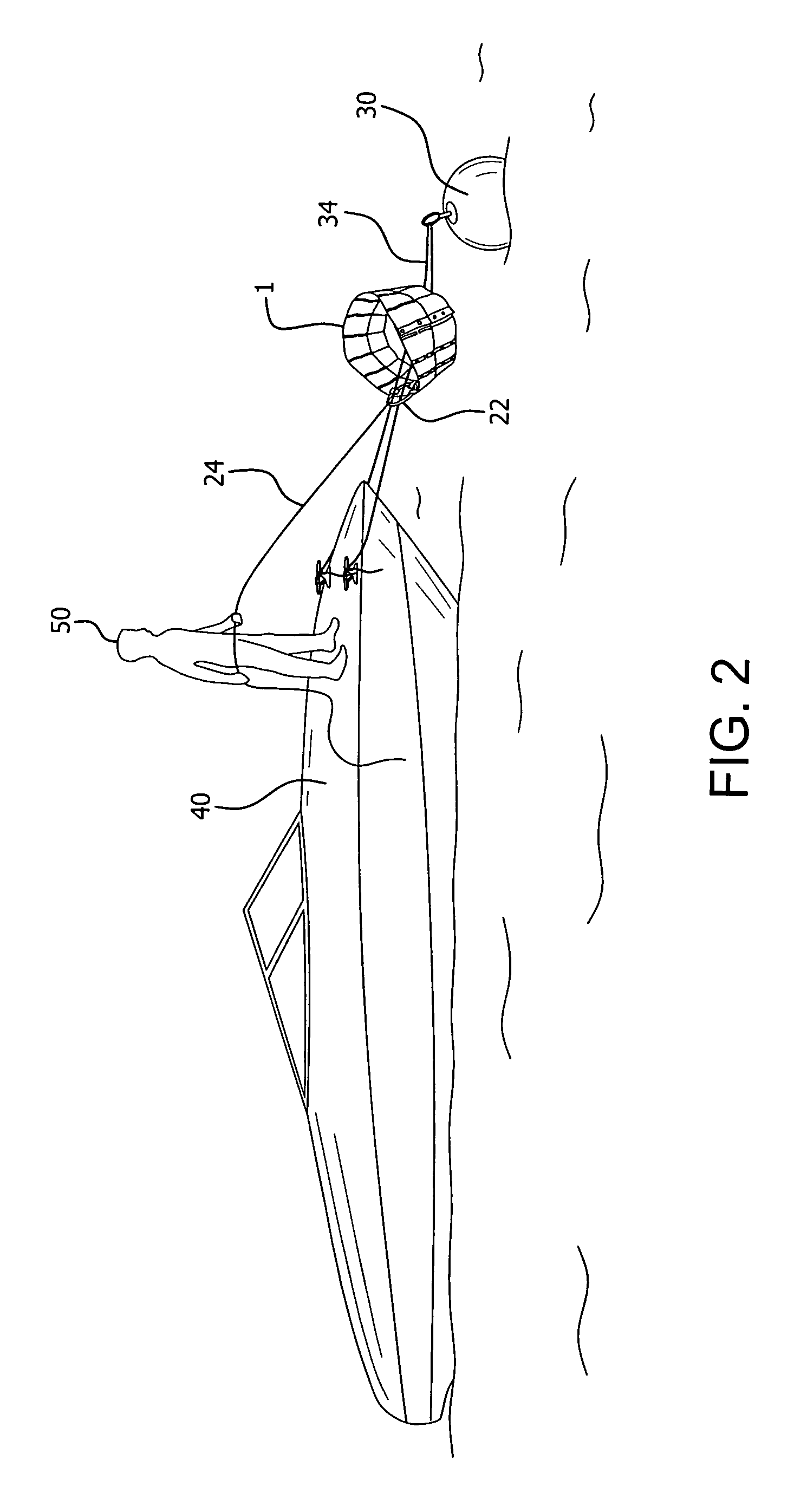
The present invention provides a protective cover for a mooring buoy that can be stored and carried on the vessel for use when needed. The cover can be easily and quickly retrieved from the buoy when the vessel is about to depart from the moorings. The cover provides complete physical and acoustic protection for the moored vessel should it come into contact with the buoy. It also prevents vessel mooring lines from becoming entangled around the buoy anchor chain.

Problems solved by technology

However, tide, wave, and wind conditions will cause the moored vessel to float around and about the buoy and, inevitably, will compel the hull of the vessel to come into contact with the buoy.
Significant noise and vessel damage is often the result of hull to buoy contact.
At the very least, vessel hulls become scraped and marred due to impact with mooring buoys.
Also, as a result of the moored vessel floating around and about the buoy, the vessel's mooring lines will inevitably become entangled around the buoy's anchor chain.
These covers eventually will deteriorate and generally lose their effectiveness.
As a practical matter, such covers are cumbersome to install and, as a practical matter, can not possibly be placed on the myriad of vessel mooring buoys in use today.
However, there is currently no protection device which is designed to be portable and stored onboard a vessel and which can be deployed from the vessel, while the vessel is actually moored to a buoy.

Method used


Image

  • Protective cover for a mooring buoy and method of deployment
  • Protective cover for a mooring buoy and method of deployment
  • Protective cover for a mooring buoy and method of deployment

Examples


Embodiment Construction

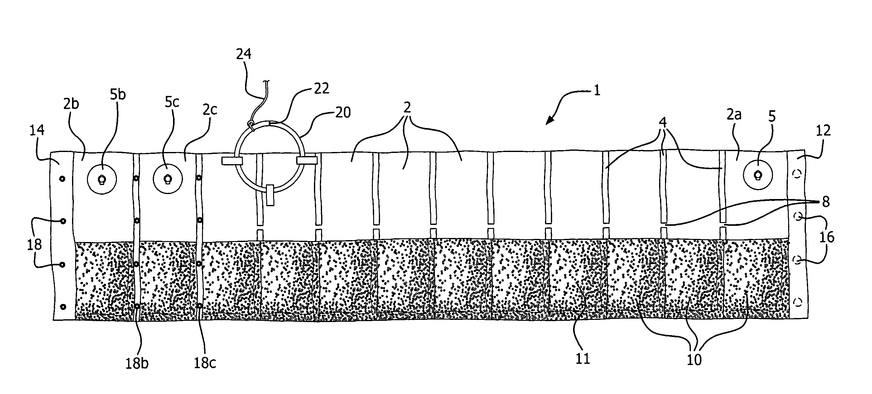
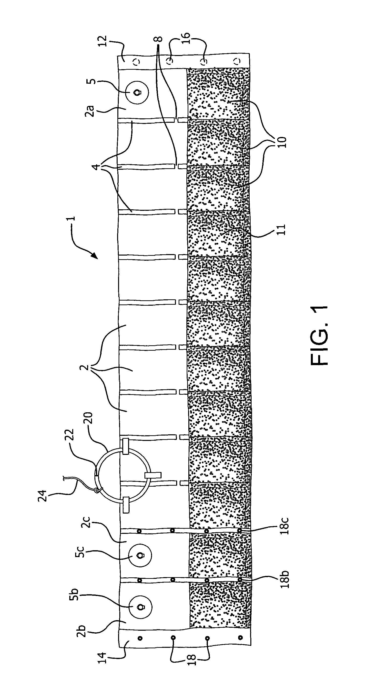
[0015]Protective buoy cover 1 comprises a plurality of air-tight, interconnected protective buoyant chambers 2, one adjacent to the other. Chambers 2 are separated by flexible spacers 4, optimally made of flexible, bendable plastic material. Chambers 2 can be air-filled sections, easily inflatable by means of air valve 5. Air entering chamber 2a via air valve 5 travels through air passages 8 within spacers 4 between the chambers, to inflate all the chambers. In lieu of inflatable sections, chambers 2 can be filled with buoyant, closed cell foam or equivalent buoyant material to provide the buoyant characteristics required for buoy cover 1. A plurality of sealed ballast filled chambers 10 is located adjacent to and beneath chambers 2. Ballast chambers 10 can be filled with sand 11 or equivalent weighted material.

[0016]Snaps or equivalent connectors 16 and 18 are configured to securely mate. These are provided at ends 12 and 14 of buoy cover 1. The connectors are designed to secure th...


PUM


Abstract

A protective cover for a mooring buoy utilizes a plurality of interconnected buoyant chambers, connected in series and separated by flexible spacers. A plurality of ballast filled chambers are located adjacent to and extend beneath the buoyant chambers. The ends of the cover are configured to be connected by snaps or equivalent attachment devices, to form a circular enclosure. A guide ring is connected to one of the buoyant chambers to allow the cover to be slid from the moored vessel, along mooring lines, and then over the buoy, such that the buoyant chambers remain at the waterline. The deployed cover thus provides protection from impact with the hull of the vessel by the buoy. A retrieval line is provided to withdraw the cover from the buoy and return it to the vessel when the vessel is departing the mooring. Included as well is the method of deploying the protective cover from a moored vessel onto a buoy.

Description

BACKGROUND OF THE INVENTION[0001]Marine vessels often tie up to anchored mooring buoys at beaches, lakes, harbors, or similar sheltered mooring areas. The usual connection between vessel and buoy consists of a mooring line, which ensures that the vessel remains secured to the buoy. However, tide, wave, and wind conditions will cause the moored vessel to float around and about the buoy and, inevitably, will compel the hull of the vessel to come into contact with the buoy. Significant noise and vessel damage is often the result of hull to buoy contact. At the very least, vessel hulls become scraped and marred due to impact with mooring buoys. Also, as a result of the moored vessel floating around and about the buoy, the vessel's mooring lines will inevitably become entangled around the buoy's anchor chain.[0002]Protective buoy covers, such as disclosed in U.S. Pat. No. 7,438,616, have been suggested. However, such covers are designed to be permanently installed over buoys. These cover...

Claims


Application Information

Patent Timeline
Patent Type & Authority Patents(United States)
IPC IPC(8): B63B22/02
CPCB63B59/02B63B2059/025B63B2241/12B63B22/02
Inventor WISHART, CHARMAINE
Owner WISHART CHARMAINE
Learn More