Aircraft engine attachment pylon having a rear engine attachment provided with a self-locking nut

a technology of rear engine attachment and pylon, which is applied in the direction of machines/engines, other domestic articles, machine supports, etc., can solve the problems of aircraft performance loss, and achieve the effect of improving aerodynamic performance and reducing the number of bolts

Inactive Publication Date: 2013-04-09
AIRBUS OPERATIONS (SAS)
View PDF27 Cites 10 Cited by
  • Summary
  • Abstract
  • Description
  • Claims
  • Application Information

AI Technical Summary

Benefits of technology

[0018]Therefore, the invention overall eliminates the lateral displacement found earlier between the first portion and the second portion of each lateral fitting.
[0020]Also, still due to the absence of offset between the first and second portions of each lateral fitting, the proposed invention offers an advantage in terms of aerodynamic performance, given that the lateral ends of the rear engine attachment body no longer need to be extended laterally as widely as in the prior art. In this respect, it is noted that the adopted design places the fixing surfaces at least in part under the caisson, thus under the lower longeron, and no longer exclusively laterally relative to the latter. Aerodynamic perturbation to the right of the rear engine attachment is thus reduced.
[0021]Said rigid structure forming a caisson preferably has two lateral panels and a longeron facing the rear engine attachment body, said longeron comprising two lateral wings mounted fixed respectively on said two lateral panels, and said first portion of each of said two lateral fittings of the rear attachment is interposed between one of said two lateral wings and its associated lateral panel. In other words, the lateral fitting is advantageously plated on either side between the two above-mentioned elements, preferably by being in contact with each of them, also allowing the assembly means passing through the first holes of the lateral fitting to be stressed in double shear, for better introduction of forces into the caisson.
[0024]Regardless, its placement below the lower longeron, thus externally relative to the caisson, allows easy access for an operator during assembly of the engine on the attachment pylon.

Problems solved by technology

This configuration implies various disadvantages, including that associated with the introduction of parasite flexion torque in the caisson, according to the longitudinal direction, precisely due to offset in the transversal direction found between the first and second portions of the lateral fittings.
Now, this configuration thus induces the lateral ends of the rear engine attachment body to constitute considerable obstacles in the flow zone of the secondary flow, and consequently causes substantial aerodynamic perturbation, causing drag, in turn leading to performance losses of the aircraft.

Method used


Image

  • Aircraft engine attachment pylon having a rear engine attachment provided with a self-locking nut
  • Aircraft engine attachment pylon having a rear engine attachment provided with a self-locking nut
  • Aircraft engine attachment pylon having a rear engine attachment provided with a self-locking nut

Examples


Embodiment Construction

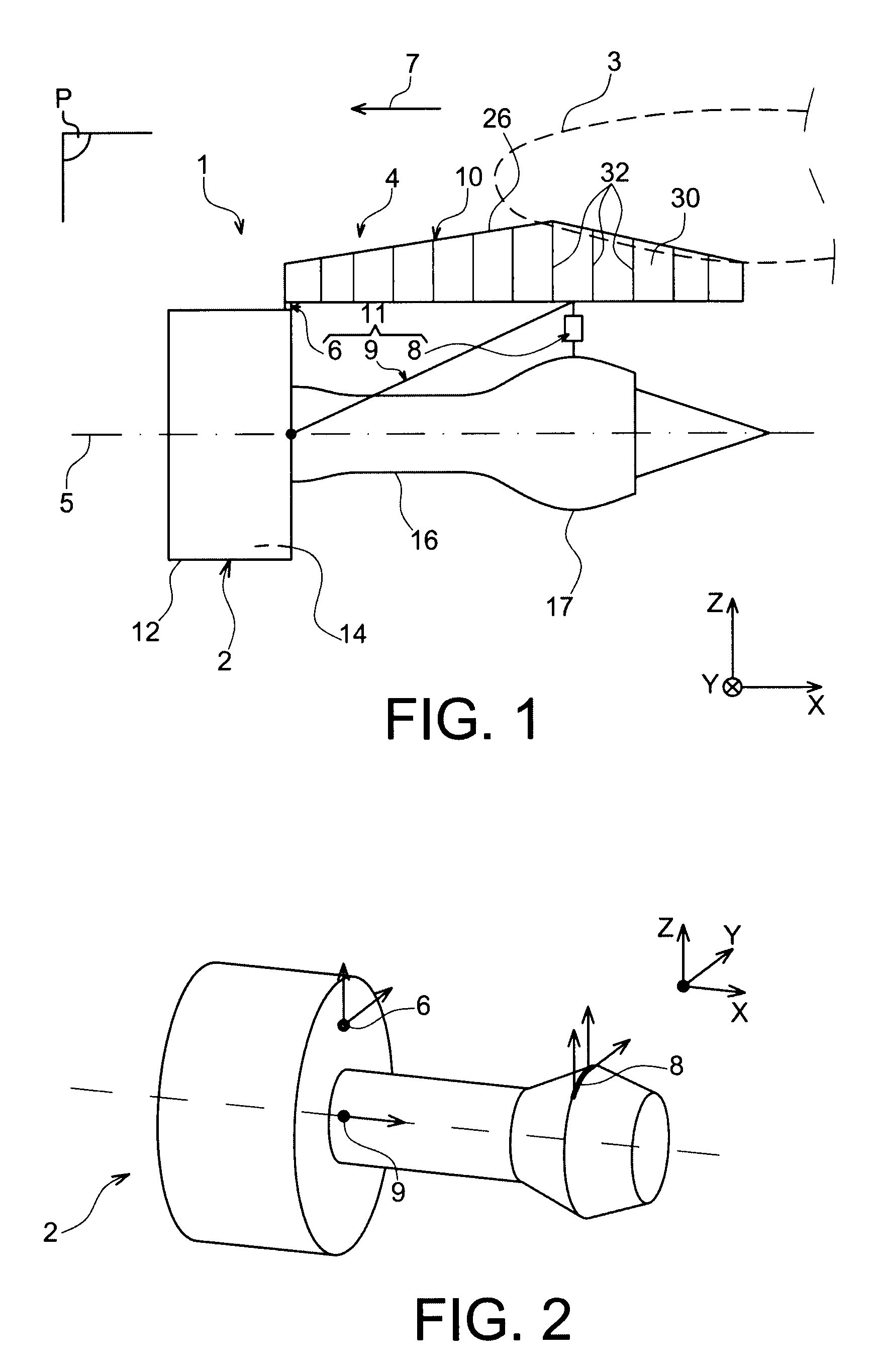
[0040]In reference to FIG. 1, this shows an aircraft engine assembly 1 to be fixed under a wing 3 of this aircraft, this assembly 1 forming an object of the present invention being provided with an attachment pylon 4 in the form of a preferred embodiment of the present invention.

[0041]Overall, the engine assembly 1 comprises an engine such as a turbojet engine 2 and the attachment pylon 4, the latter being especially fitted with a rigid structure 10 and an engine-mounting system 11 composed of a plurality of engine attachments 6, 8 and a thrust force collection device 9 generated by the turbojet engine 2, the assembly system 11 therefore being interposed between the engine and the abovementioned rigid structure 10, the latter also being called a primary structure. By way of indication, it is noted that the assembly 1 is intended to be enclosed by a nacelle (not shown in this figure), and that the attachment pylon 4 comprises another series of attachments (not shown) ensuring suspens...


PUM


Abstract

An aircraft engine attachment pylon including a rigid structure forming a caisson, and a rear engine attachment including an attachment body and at least one lateral fitting arranged on either side of the caisson. Each fitting includes a first portion pierced by first assembly holes enabling it to be fixed to the caisson, and a second portion defining a fixing surface of the body. The second portion includes a housing orifice receiving a self-locking nut cooperating with a screw supported against the body and, in transversal section, an axis of the screw passes through the first holes.

Description

TECHNICAL FIELD[0001]The present invention relates in general to an aircraft engine assembly, of the type comprising an engine, an attachment pylon and an engine-mounting system provided with a plurality of engine attachments and being interposed between a rigid structure of the attachment pylon and the engine.[0002]The invention also relates to such an aircraft engine attachment pylon.[0003]The invention can be used on any type of aircraft equipped for example with turbojet engines or of turboprop engines.[0004]This type of attachment pylon, also known as “EMS” (“Engine Mounting Structure”), for example suspends a turboengine below the wing of the aircraft, or else mounts this turboengine above this same wing.PRIOR ART[0005]Such an attachment pylon is in fact provided to constitute the linkage interface between an engine such as a turbojet engine and a wing of the aircraft. It transmits to the structure of this aircraft the forces generated by its associated turbojet engine, and al...

Claims


Application Information

Patent Timeline
Patent Type & Authority Patents(United States)
IPC IPC(8): B64D27/00
CPCB64D27/26B64D2027/266
Inventor MARTINOU, JEAN-MARCBERJOT, MICHAEL
Owner AIRBUS OPERATIONS (SAS)
Why Eureka
Try Eureka