
Method, particularly for manufacturing terminals for electric resistors, and the terminal obtained

a technology of manufacturing terminals and resistors, which is applied in the direction of resistors, non-adjustable resistors, contact member manufacturing, etc., can solve the problems of poor workability of pure copper, poor economy of working materials, and high cost, and achieve the effect of improving economics

Active Publication Date: 2013-04-02
BONAITI
View PDF14 Cites 0 Cited by
  • Summary
  • Abstract
  • Description
  • Claims
  • Application Information

AI Technical Summary

Benefits of technology

The present invention aims to provide a method for producing terminals for electric resistors that is cost-effective and efficient, using less valuable material. The method allows for the use of substantially pure copper while ensuring good productivity and finish. It is also simple and easy to implement, and can be done at low cost. The invention provides a terminal that is easy to solder to electric resistors. The method involves reducing the thickness of the material by cold pressing, to create a thin and thick part that forms the tip of the terminal. This results in a thinner terminal that is easier to join with other components.

Problems solved by technology

Indeed because of the poor workability of pure copper, and in particular because of the propensity to being used as a material to be turned, it is generally alloyed with tellurium or other materials.
However, the technique used today for producing terminals for electric resistors, which consists in turning pieces made from copper and tellurium alloy, exhibits some drawbacks, including the poor economy of the working material, which can be ascribed to the losses of swarf owing to the choice of turning as a technique for forming the terminals.
Furthermore, nowadays copper and tellurium alloy is relatively valuable and hence it costs more, for example, than pure copper.

Method used


Image

  • Method, particularly for manufacturing terminals for electric resistors, and the terminal obtained
  • Method, particularly for manufacturing terminals for electric resistors, and the terminal obtained
  • Method, particularly for manufacturing terminals for electric resistors, and the terminal obtained

Examples


Embodiment Construction

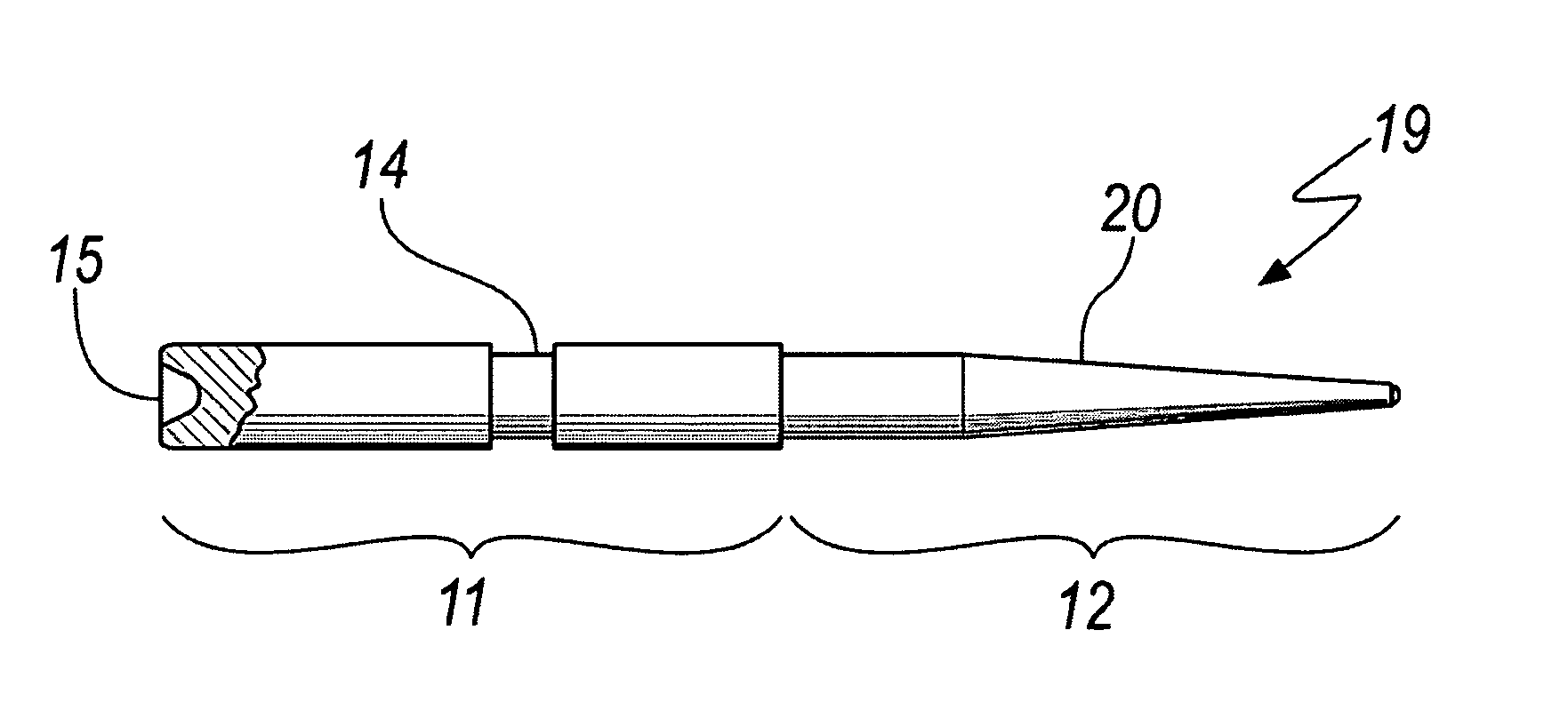
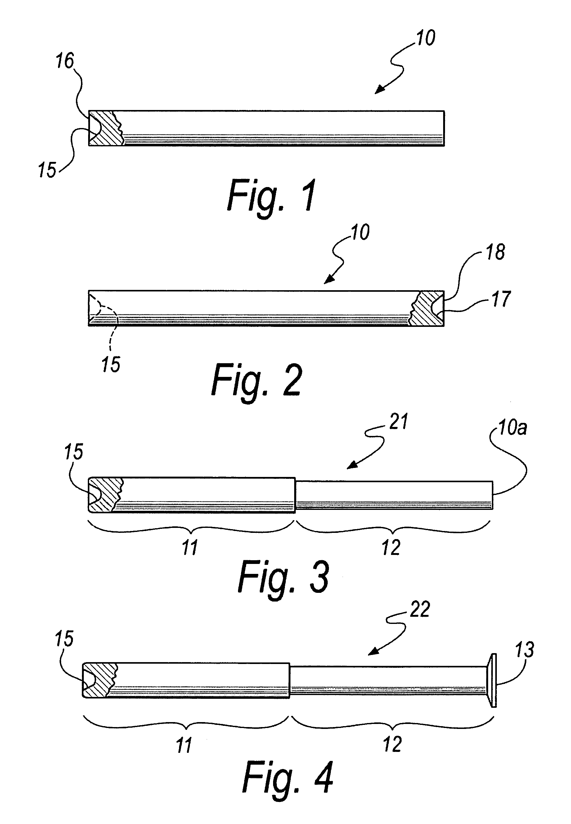
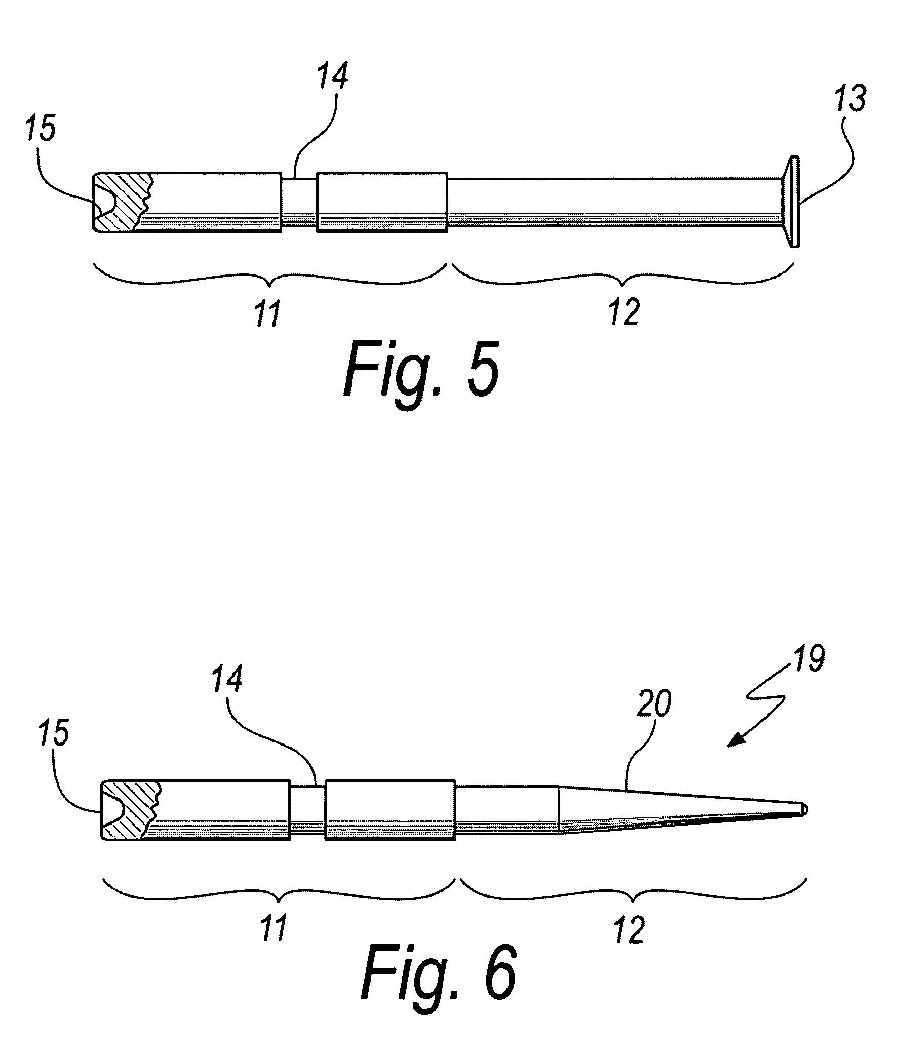
[0023]With reference to the figures, a method, particularly for the production of terminals for electric resistors, according to the invention has a peculiarity in that it consists in[0024]preparing a piece 10 of substantially pure copper,[0025]reducing the thickness, by conveniently longitudinal cold pressing, of the piece 10 so as to obtain from it a thick part 11 and a thin part 12 which are consecutive, the thin part 12 being designed to form the tip of an electrical terminal to be obtained, the operation of reducing the thickness being preferably performed by means of longitudinal cold pressing of a portion of the piece 10 which comprises one of its ends 10a, [0026]advantageously, forming, by conveniently front cold pressing, a head 13 that can be used for handling the piece and is formed on the thin portion 12,[0027]obtaining, by rolling, a groove 14, in a substantially central position of the thick part 11,[0028]tapering, by rolling, the thin portion 12, conveniently also rem...


PUM

PropertyMeasurementUnit
thicknessaaaaaaaaaa
thickaaaaaaaaaa
workabilityaaaaaaaaaa

Abstract

A method for manufacturing terminals for electric resistors consists inpreparing a piece of substantially pure copper;reducing the thickness, by cold pressing, of the piece so as to obtain from it at least one thick part and one thin part designed to form the tip of an electrical terminal to be obtained;obtaining, by rolling, a groove which is central to the thick part; and tapering, by rolling, the thin portion.

Description

[0001]The present invention relates to a method, particularly for manufacturing terminals for electric resistors, and to the terminal produced.BACKGROUND OF THE INVENTION[0002]Nowadays, terminals for electric resistors are produced by performing turning operations on pieces of wire or a rod of copper alloy.[0003]Indeed because of the poor workability of pure copper, and in particular because of the propensity to being used as a material to be turned, it is generally alloyed with tellurium or other materials.[0004]Such alloy of copper and tellurium thus makes it possible to impose a cutting speed that results in profitable productivity, furthermore making it possible to achieve a satisfactory finish of the worked pieces.[0005]However, the technique used today for producing terminals for electric resistors, which consists in turning pieces made from copper and tellurium alloy, exhibits some drawbacks, including the poor economy of the working material, which can be ascribed to the los...

Claims


Application Information

Patent Timeline
Patent Type & Authority Patents(United States)
IPC IPC(8): H01C1/14
CPCH01R13/03H01R13/04H01R13/6616H01R43/16B21H7/00B21H7/182B21K23/00Y10T29/49204Y10T29/49082
Inventor BONAITI, LUCA
Owner BONAITI
Learn More