
Seal arrangement for filter element; filter element assembly; and, methods

a filter element and sealing arrangement technology, applied in the field of air cleaners, can solve the problems of disturbing the stability of flow pass the air flow sensor and the amount of force needed

Active Publication Date: 2013-04-02
DONALDSON CO INC
View PDF168 Cites 56 Cited by
  • Summary
  • Abstract
  • Description
  • Claims
  • Application Information

AI Technical Summary

Problems solved by technology

In some instances, the amount of force needed to install an element having a seal profile in accord with FIGS. 1, 3, 4, 7, 9, 10, 26 and 27, can be undesirable.
It has been found that when housing seal arrangements are molded in accord with the profiles of FIGS. 1, 3, 4, 7, 9, 10, 26 and 27, in some instances inwardly positioned regions of molded urethane can provide undesirable levels of inconsistent flash thereby disturbing the stability of flow pass the air flow sensor an unacceptable amount.

Method used


Image

  • Seal arrangement for filter element; filter element assembly; and, methods
  • Seal arrangement for filter element; filter element assembly; and, methods
  • Seal arrangement for filter element; filter element assembly; and, methods

Examples


Embodiment Construction

I. General Information

[0049]The present disclosure relates to filter elements useable in air cleaner assemblies. In general, the preferred filter elements of concern herein are those in which: (a) the media of the elements comprises a first fluted (typically folded or corrugated) sheet of media attached to a second sheet of media (typically a flat media or nearly flat media) to form a single facer; and (b) in which the single facer combination is either wound or stacked, to create a media arrangement comprising a plurality of inlet flutes open at an inlet end or face of the filter media and closed at or near (typically within 10% of the total length of the inlet flutes of) the outlet and / or face of the media; and, a plurality of outlet flow flutes sealed closed at or near the inlet and / or face of the media (i.e., typically within 10% of the total length of the outlet flutes of the inlet and / or face), and open at the outlet end or face of the media. Typically the media pack is also c...


PUM

PropertyMeasurementUnit
angleaaaaaaaaaa
lengthaaaaaaaaaa
distanceaaaaaaaaaa

Abstract

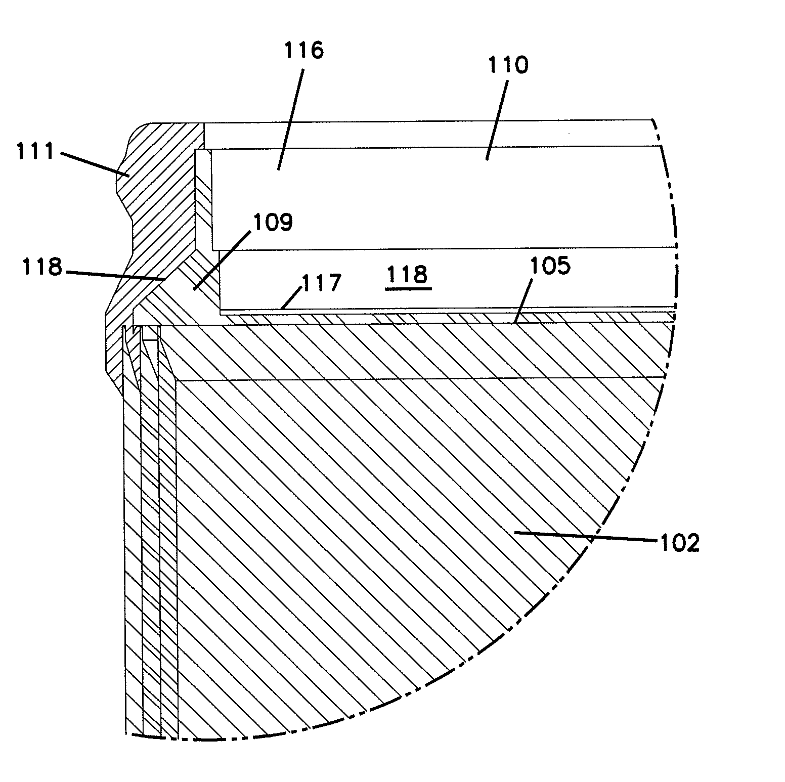
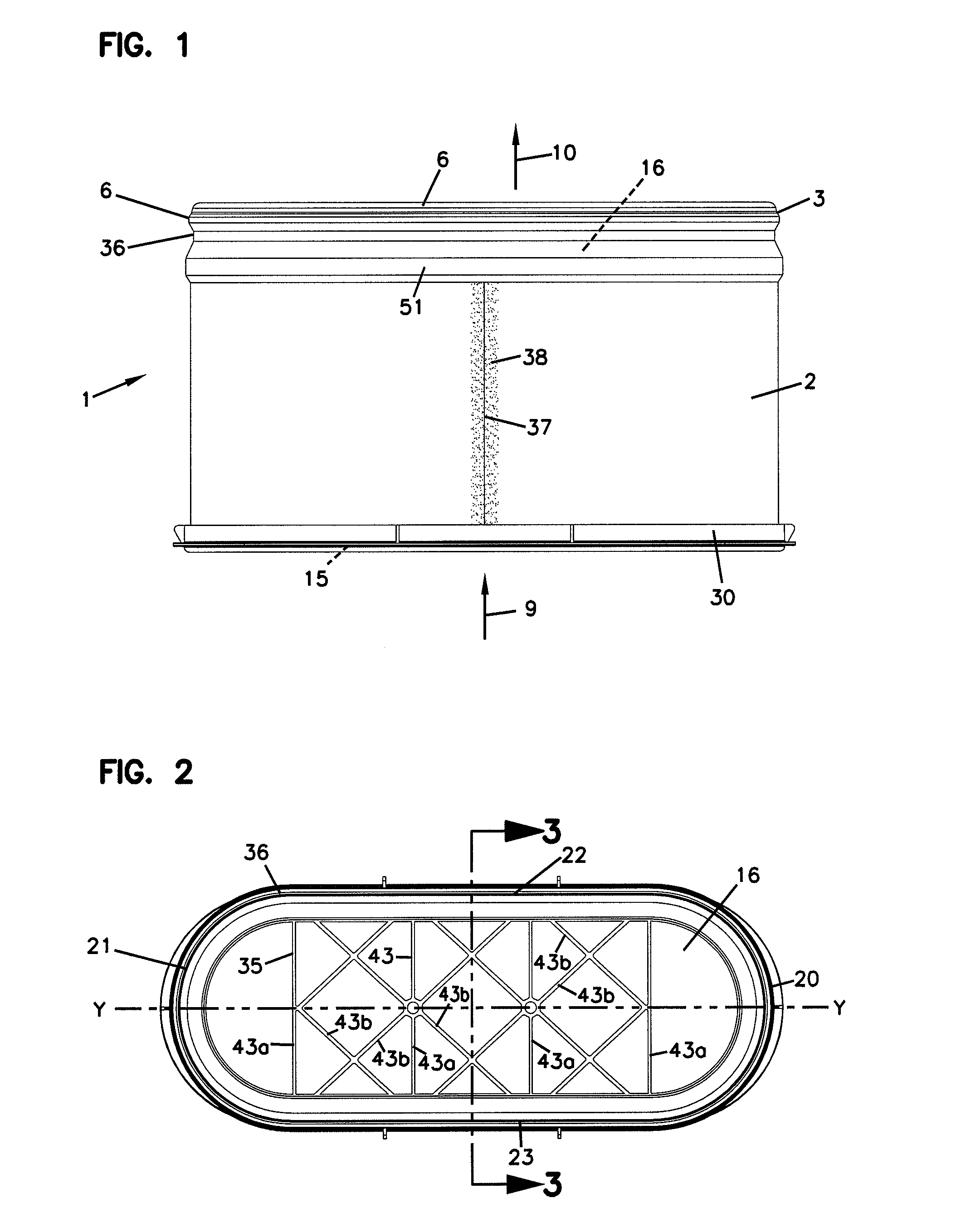
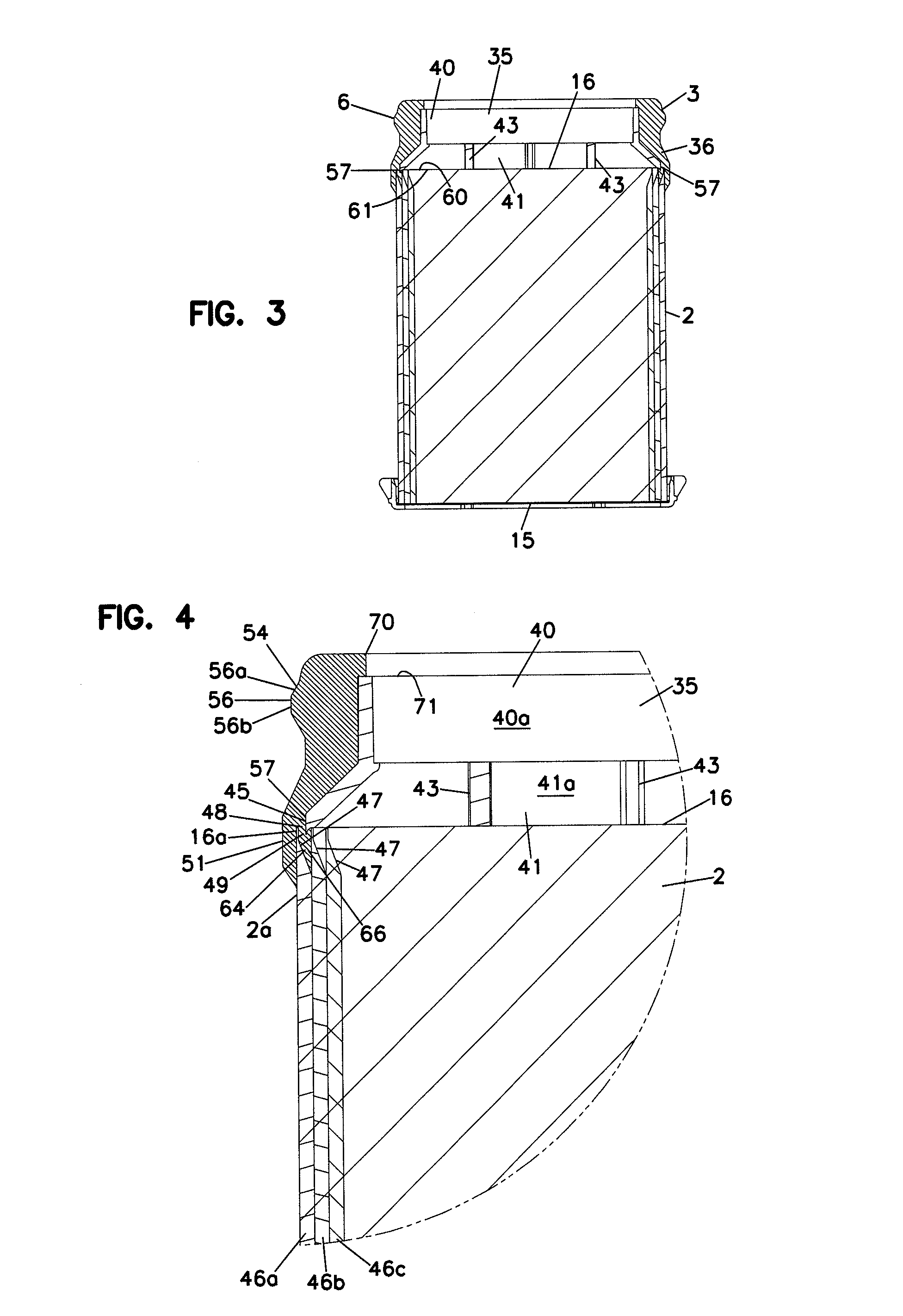
A filter cartridge arrangement is provided which includes a media pack comprising Z-filter media, a preform and a housing seal member. Improvements in the preform and seal member are described which include: a single beveled surface of the seal member to facilitate installation; and, an inside region of the seal member having a tip adjacent in inwardly directed lip of the preform, to control flash during molding. A variety of media pack configurations and features are described.

Description

CROSS-REFERENCE TO RELATED APPLICATION[0001]This application is being filed on 7 May 2008, as a U.S. National Stage of PCT International Patent application no. PCT / US2006 / 043836, filed on 8 Nov. 2006 in the name of Donaldson Company, Inc., a U.S. national corporation, applicant for the designation of all countries except the US, and Benny Kevin Nelson, Sheldon Anderson, Thomas G. Miller, Ross Norman Anderson, and John Orlin Kirkwold, all citizens of the U.S., applicants for the designation of the US only, and a claim of priority, to the extent appropriate, is made to U.S. Provisional Patent Application Ser. No. 60 / 735,650, filed Nov. 9, 2005. PCT / US2006 / 043836 and U.S. 60 / 735,650 are incorporated herein by reference.[0002]The present application includes disclosure discussed in U.S. Publication US 2005 / 0166561 A1, published Aug. 4, 2005, PCT Publication WO 05 / 63361, published Jul. 14, 2005, U.S. Pat. No. 6,190,432 and European Patent EP 1 159 052, each of which is incorporated herei...

Claims


Application Information

Patent Timeline
Patent Type & Authority Patents(United States)
IPC IPC(8): B01D39/00
CPCB01D46/0001B01D46/0004B01D46/10B01D46/525B01D46/527F02M35/0203B01D2279/60F02M35/024B01D2271/027B01D46/0005B01D46/2411B01D46/2414B01D46/521
Inventor NELSON, BENNY KEVINANDERSON, SHELDONMILLER, THOMAS G.ANDERSON, ROSS NORMANKIRKWOLD, JOHN ORLINSCHRAGE, KEVINMURPHY, TROYMORK, DONALD RAYMONDOSENDORF, RICHARD J.
Owner DONALDSON CO INC
Learn More