
Cup component of an orthopaedic joint prosthesis

a technology of orthopaedic joints and components, applied in the field of orthopaedic joint prosthesis components, can solve the problems of inability to use fixation techniques, quality or quantity of bone tissue, etc., and achieve the effect of minimising the size of the flang

Active Publication Date: 2013-04-02
DEPUY (IRELAND) LTD
View PDF66 Cites 3 Cited by
  • Summary
  • Abstract
  • Description
  • Claims
  • Application Information

AI Technical Summary

Benefits of technology

The present invention increases the accuracy and stability of placing a shell in a patient's bone during a surgical procedure. It uses an inserter instrument to locate the shell accurately and hold it in position while drilling bores in the bone. A temporary screw with a self-drilling tip is used to hold the shell in place without having to form a bore first. A drill guide is used to control the alignment of a drill bit and protect the threads in the bone. An adaptor is used to create a secure path for the temporary screw by engaging with pre-existing bores in the bone. The invention also includes a threaded stent that can securely hold the shell in the patient's bone cavity while drilling and placing fixation screws. The design of the thread on the fixation screws ensures the shell is held securely. Overall, this invention improves the precision and stability of placing a shell in a patient's bone during surgery.

Problems solved by technology

However such fixation techniques cannot be used when the quality or the quantity of the bone tissue underlying the cup component is deficient.

Method used


Image

  • Cup component of an orthopaedic joint prosthesis
  • Cup component of an orthopaedic joint prosthesis
  • Cup component of an orthopaedic joint prosthesis

Examples


Embodiment Construction

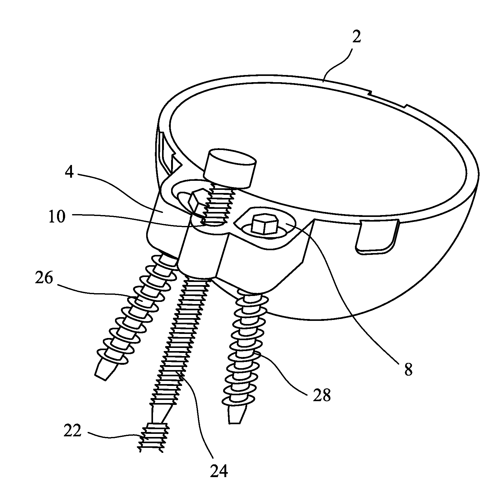
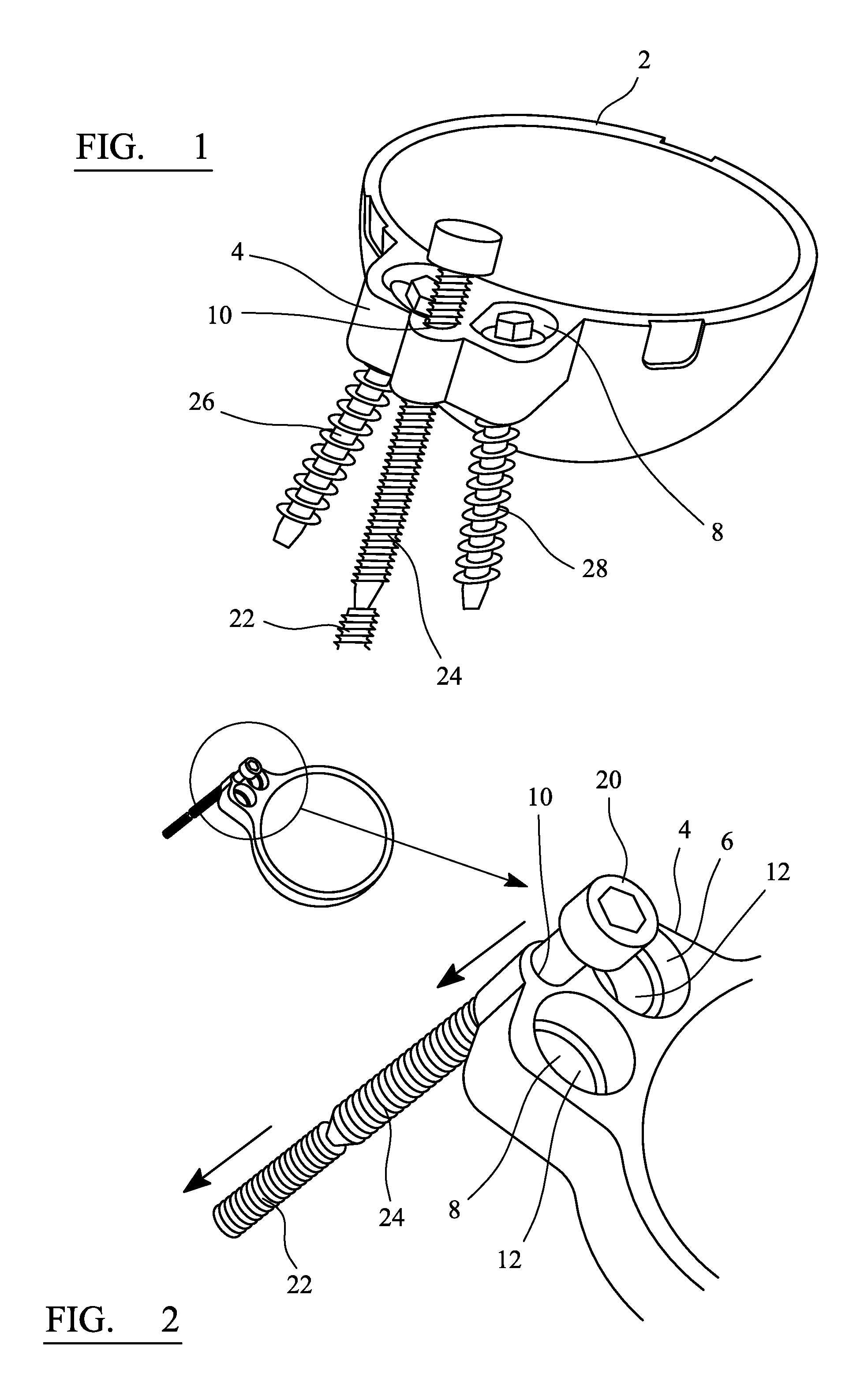
[0057]Referring to the drawings, FIGS. 1 and 2 show the shell 2 of an acetabular cup component of a hip joint prosthesis. The shell has an outwardly extending flange 4 at its open face. The flange has three bores formed in it. First and second bores 6, 8 have a larger diameter than a third bore 10. The third bore is located between the first and second bores, displaced outwardly from the first and second bores.

[0058]As shown in FIG. 2, each of the first and second bores 6, 8 has a bearing surface 12 which is defined by part of a sphere. The first and second bores can receive bushings which have an external surface which is defined by part of a sphere. The bushings can be articulated within their respective bores by virtue of the mating spherical surfaces on the bushings and the bores. These features are also incorporated in the embodiment which is shown in FIGS. 8 to 12 and are described below in relation to that embodiment.

[0059]The bushings have a threaded bore which extends throu...


PUM


Abstract

A cup component of an orthopaedic joint prosthesis comprises a hollow shell wherein the head part of a mating component of the joint can be received. The shell has a flange at its open face extending around at least part of its periphery with at least two major threaded bores extending through the flange. The flange also provides at least one minor threaded bore, wherein the diameter of the minor bore is less than that of the major bores and the pitch of the thread in the minor bore is less than that of the thread in the major bores. The cup component includes at least two fixation screws whose shanks have approximately equal diameters, each of which is threaded on its external surface (i) to engage the thread a respective one of the bores in the shell flange, and (ii) to threadingly engage the bone, and a temporary screw having a self-drilling tip for forming a bore in a bone, and a diameter and a thread which are suitable for threadingly engaging the thread in the minor bore.

Description

CROSS REFERENCE TO RELATED APPLICATION[0001]This application is a National Stage 35 U.S.C. 371 of International Patent Application PCT / EP2009 / 001588, filed Feb. 26, 2009.BACKGROUND OF THE INVENTION[0002]This invention relates to a cup component of an orthopaedic joint prosthesis.[0003]Orthopaedic joint prostheses for replacement of joints such as the hip and shoulder joints generally comprise a cup component and a mating component which has a convex head which can be received in the cup and can articulate relative to the cup. For example a hip joint prosthesis can comprise a femoral component having a stem part which can be implanted in the intramedullary canal of the femur and a head part on a neck which is inclined to the axis defined by the intramedullary canal. The joint prosthesis includes an acetabular component which comprises a metal shell which is fixed within the patient's acetabulum and a bearing part, frequently formed from a polymeric material such as ultrahigh molecula...

Claims


Application Information

Patent Timeline
Patent Type & Authority Patents(United States)
IPC IPC(8): A61F2/32
CPCA61B17/1746A61F2/34A61B17/8033A61F2/4611A61F2002/30578A61F2002/30672A61F2002/30787A61F2002/3432A61B2017/1778A61B17/1778
Inventor DIVOUX, LAURENT
Owner DEPUY (IRELAND) LTD
Learn More