Optical signal quality monitoring

a quality monitoring and optical signal technology, applied in the field of optical signal quality monitoring method and optical signal quality monitoring apparatus, can solve the problems of inability to accurately estimate q value, inability to definitively avoid polarization-mode dispersion at present, and significant affect the quality of a signal received, etc., to achieve accurate estimation, quality value, and variation in the quality of optical signals

Active Publication Date: 2013-03-26
NEC CORP
View PDF7 Cites 4 Cited by
  • Summary
  • Abstract
  • Description
  • Claims
  • Application Information

AI Technical Summary

Benefits of technology

[0012]Therefore, an object of the present invention is to provide an optical signal quality monitoring apparatus and an optical signal quality monitoring method capable of accurately monitoring variations in the quality of an optical signal caused by polarization-mode dispersion even when a high-order component of polarization-mode dispersion is not negligible.
[0015]According to the present invention, a quality value can be accurately estimated from a measurement value based on a value measured from an optical transmission signal and therefore variations in the quality of the optical signal caused by polarization-mode dispersion can be accurately monitored.

Problems solved by technology

In such an ultrahigh-speed optical communication system, even slight waveform degradation can significantly affect the quality of a signal received.
However, there is no definitive way of avoiding polarization-mode dispersion at present.
The techniques disclosed in the documents given above cannot accurately estimate a Q value if a high-order component of polarization-mode dispersion is not negligible.
Therefore, it is difficult to apply the methods disclosed in J. C. Rasmussen et. al., “Automatic Compensation of Polarization-Mode Dispersion for 40 Gb / s Transmission Systems,” p.
However, when applied to Q-value monitoring, the accuracy of the monitoring by the method disclosed in JP2004-138615A is low.
This is because the method does not take into consideration a high-order component of polarization-mode dispersion.
However, when a high-order component of polarization-mode dispersion is not negligible, the correlation between SOP and a Q value varies depending on the magnitude of the first-order component of polarization-mode dispersion and therefore is not constant.
Assuming that the correlation between SOP and Q value is constant when a high-order component of polarization-mode dispersion is not negligible, a large error is introduced in estimating a Q value from an SOP.
Using a Q value having a large estimation error makes optical signal quality information imprecise.
As a result, network control, such as failure recovery, based on the optical signal quality information can become difficult and the reliability of the optical network can degrade.

Method used


Image

  • Optical signal quality monitoring
  • Optical signal quality monitoring
  • Optical signal quality monitoring

Examples


Embodiment Construction

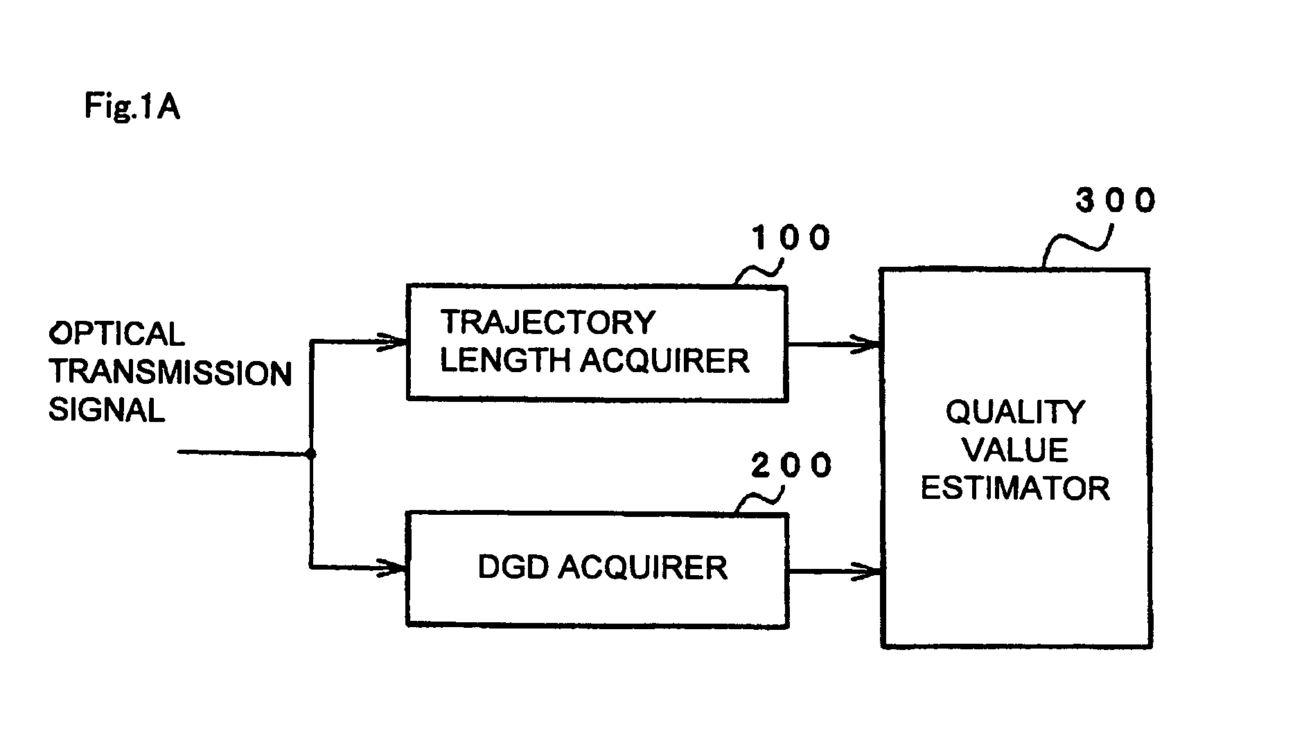
[0035]FIG. 1A is a block diagram showing a basic configuration of an optical signal quality monitoring apparatus according to the present invention. In the configuration shown in FIG. 1A, the optical signal quality monitoring apparatus includes trajectory length acquirer 100 (implemented by SOP length monitor 1103 shown in FIG. 4) which measures the Stokes vector of an optical transmission signal over an optical signal modulation frequency band and acquires the length of the trajectory in the optical signal modulation frequency band traced out by the measured Stokes vector on a Poincare sphere (for example SOP length) as a measurement value, DGD acquirer 200 (implemented by CPU 1302 shown in FIG. 3) which acquires the DGD of an optical signal whose Stokes vector is measured by trajectory length acquirer 100, and quality value estimator 300 (implemented by CPU 1302 shown in FIG. 4) which estimates a quality value (for example a Q value) by using the length of the trajectory acquired ...


PUM


Abstract

An optical signal quality monitoring apparatus includes a trajectory length acquirer measuring a Stokes vector of an optical transmission signal over an optical signal modulation frequency band and acquiring the length of a trajectory in the optical signal modulation frequency band traced out on a Poincare sphere by the measured Stokes vector as the measurement value; a DGD acquirer acquiring a DGD value of the optical transmission signal the Stokes vector of which is measured by the trajectory length acquirer; and a quality value estimator estimating a quality value by using the length of the trajectory acquired by the trajectory length acquirer and the DGD value acquired by the DGD acquirer.

Description

BACKGROUND OF THE INVENTION[0001]1. Field of the Invention[0002]The present invention relates to an optical signal quality monitoring method and an optical signal quality monitoring apparatus that monitor the quality of an optical signal in an optical communication system and, in particular, to an optical signal quality monitoring apparatus and an optical signal quality monitoring method that monitor the quality of an optical signal by using a value estimated from a polarization state.[0003]2. Description of the Related Art[0004]With the expansion of communication capacities, optical communications at a transmission rate exceeding 10 Gb / s per optical signal channel have been put into commercial use and research and development of optical communications at a transmission rate exceeding 100 Gb / s is being actively conducted. In such an ultrahigh-speed optical communication system, even slight waveform degradation can significantly affect the quality of a signal received. Physical pheno...

Claims


Application Information

Patent Timeline
Patent Type & Authority Patents(United States)
IPC IPC(8): G08B17/12H04B10/032H04B10/079H04B10/07H04B10/2507H04B10/2569H04B10/524H04B10/54H04B10/58
CPCH04B10/07953
Inventor TAKESHITA, HITOSHI
Owner NEC CORP
Why Eureka
Try Eureka