
Charge device, electronic device and charge method thereof

a technology of electronic devices and rechargeable devices, which is applied in the direction of electric power, electric vehicles, transportation and packaging, etc., can solve the problems of excessive low voltage of rechargeable devices, damage to rechargeable devices, and inability to achieve power charging effect, so as to avoid damage or explosion of rechargeable devices

Inactive Publication Date: 2013-03-19
BEYOND INNOVATION TECH
View PDF5 Cites 2 Cited by
  • Summary
  • Abstract
  • Description
  • Claims
  • Application Information

AI Technical Summary

Benefits of technology

[0008]The invention is directed to a charge device, an electronic device and a charge method, which may avoid damage or explosion of a rechargeable device caused by overheating, and may complete charging the rechargeable device that is temporarily over-discharged.
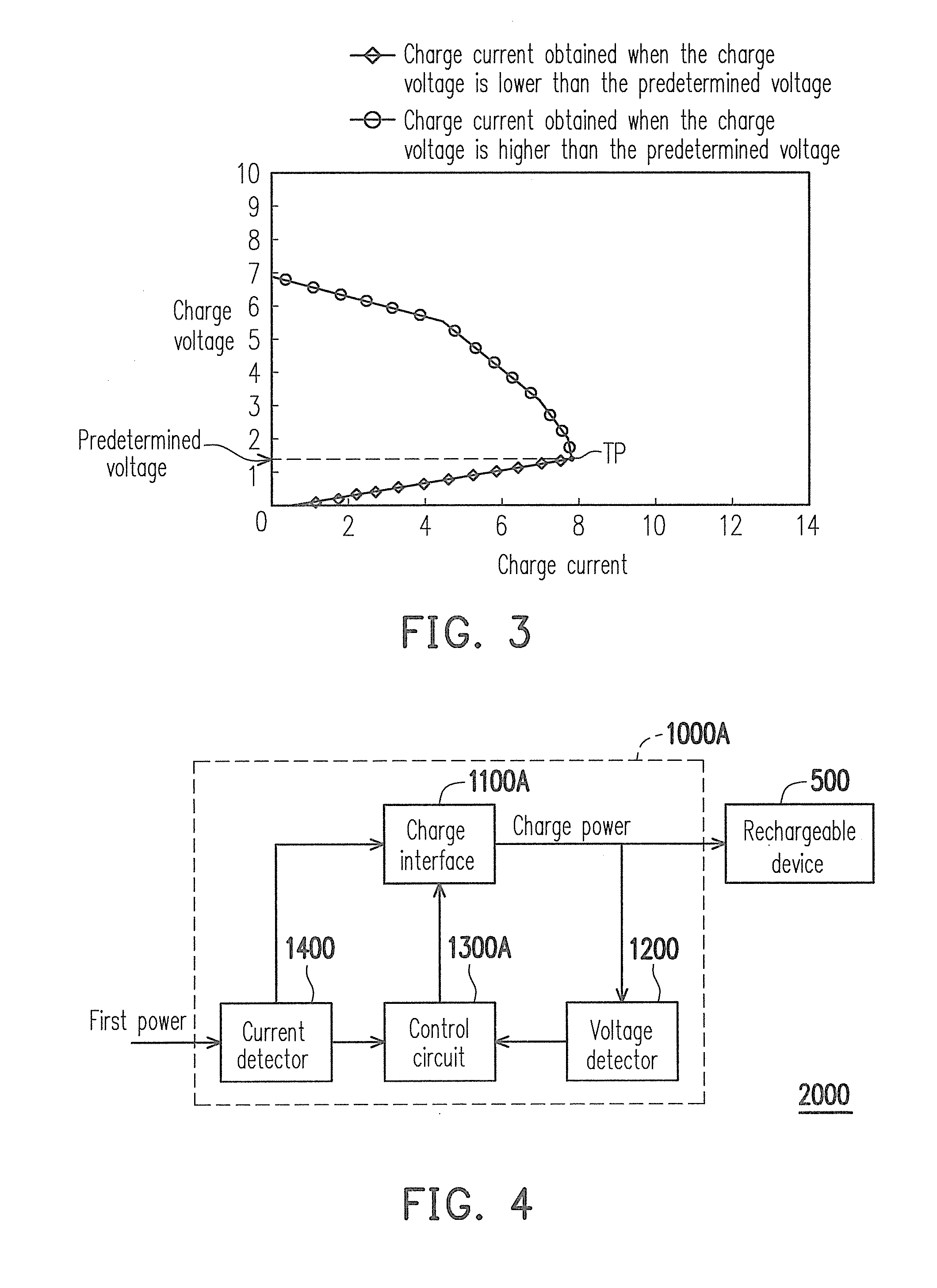
[0026]According to the above descriptions, the invention provides a charge device, an electronic device and a charge method. In allusion to abnormity and malfunction of the rechargeable device, when the voltage detector detects that the charge voltage is smaller than the predetermined voltage, the control circuit limits the charge current. Therefore, utilization of the charge device can avoid damage or explosion of the rechargeable device caused by overheating. On the other hand, regarding a temporary over-discharge of the rechargeable device, when the voltage detector detects that the charge voltage is smaller than the predetermined voltage, the control circuit limits the charge current. The charge device has a chance to recover the charge voltage to a voltage level greater than the predetermined voltage, and then the rechargeable device is charged according to a general charge method.

Problems solved by technology

However, when the rechargeable device is abnormal or in malfunction, the voltage of the rechargeable device can be excessively low, and now if a large current is used to charge the rechargeable device, not only a power charging effect cannot be achieved, but also the rechargeable device can be damaged due to overheating, or even exploded to raise a safety concern.

Method used


Image

  • Charge device, electronic device and charge method thereof
  • Charge device, electronic device and charge method thereof
  • Charge device, electronic device and charge method thereof

Examples


Embodiment Construction

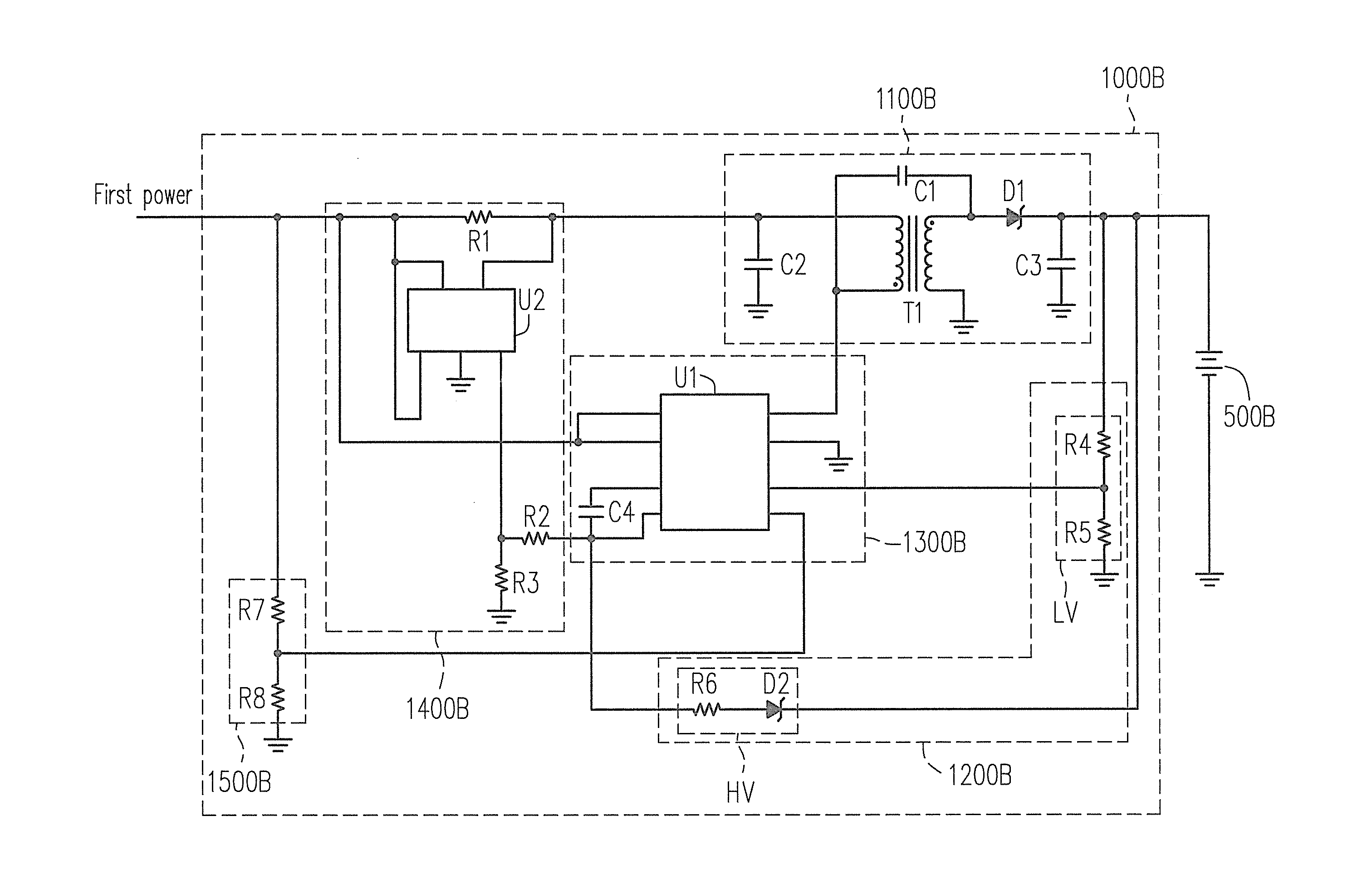
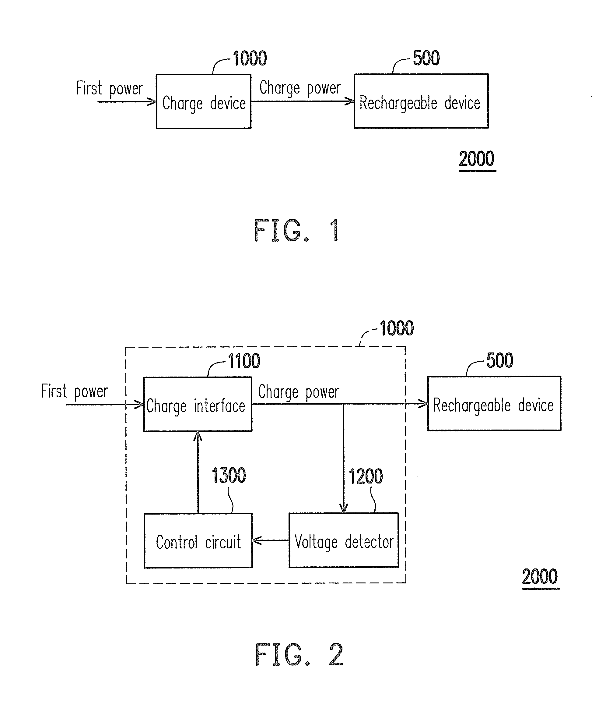
[0037]FIG. 1 is a block diagram illustrating an electronic device according to an embodiment of the invention. Referring to FIG. 1, the electronic device 2000 includes a rechargeable device 500 and a charge device 1000. The electronic device 2000 is, for example, a portable mobile device such as a mobile phone, a personal digital assistant (PDA), a multimedia player, a notebook, or a netbook, etc., but the invention is not limited thereto. FIG. 2 is a block diagram illustrating a charge device according to an embodiment of the invention. Referring to FIG. 2, the charge device 1000 includes a charge interface 1100, a voltage detector 1200 and a control circuit 1300. A first power may be an alternating current. The charge interface 1100 receives the first power and converts it into the direct current power, so as to provide a charge power to charge the rechargeable device 500. The voltage detector 1200 detects a charge voltage of the rechargeable device 500. The control circuit 1300 i...


PUM


Abstract

A charge device is provided. The charge device includes a charge interface, a voltage detector and a control circuit. The charge interface receives a first power and provides a charge power to charge a rechargeable device accordingly. The voltage detector detects a charge voltage of the rechargeable device. The control circuit is respectively coupled to the charge interface and the voltage detector. When the charge voltage is smaller than a predetermined voltage, the control circuit makes the charge voltage and a charge current of the charge power to present a proportional relation. An electronic device and a charge method are also provided.

Description

CROSS-REFERENCE TO RELATED APPLICATION[0001]This application claims the priority benefit of Taiwan application serial no. 98138643, filed on Nov. 13, 2009. The entirety of the above-mentioned patent application is hereby incorporated by reference herein and made a part of this specification.BACKGROUND[0002]1. Field of the Invention[0003]The present invention relates to a charge device, an electronic device and a charge method. More particularly, the present invention relates to a charge device, an electronic device and a charge method capable of controlling the charge current.[0004]2. Description of Related Art[0005]Mobile devices have changed life styles of people around the world, and in nowadays, almost everyone has a portable mobile device, for example, a personal digital assistant (PDA), a global positioning system (GPS), a notebook, a netbook or a mobile phone, etc. The portable mobile device generally includes a rechargeable device used for providing power to the mobile devic...

Claims


Application Information

Patent Timeline
Patent Type & Authority Patents(United States)
IPC IPC(8): H02J7/04H02J7/06
CPCH02J7/022H02J7/045H02J7/02H02J2207/20H02J7/04H02J7/00714H02J7/007182
Inventor HUNG, CHIEN-PANGHU, CHIH-CHIEHLIN, CHIU-YUAN
Owner BEYOND INNOVATION TECH
Learn More