
Rotationally asymmetric bone screw

a bone screw and rotational asymmetry technology, applied in the field of bone screw, can solve the problems of loss of stability and increased stress on the screw-bone interface, and achieve the effect of reducing the risk of fractur

Inactive Publication Date: 2013-03-19
APEX BIOMEDICAL
View PDF59 Cites 22 Cited by
  • Summary
  • Abstract
  • Description
  • Claims
  • Application Information

AI Technical Summary

Benefits of technology

The present invention relates to a bone screw with features that provide a secure but flexible engagement with a bone plate. The technical effects of the invention include improved stability and reduced stress on the bone-screw interface, as well as increased flexion at the fracture site to promote fracture healing. The invention also addresses the issue of stiffness and its impact on stress and motion at the fracture site, and provides various configurations for slotted bone screws to achieve secure engagement with the bone plate.

Problems solved by technology

Loosening of the screws in the bone or a resorption of the bone may thus easily lead to a loss of stability.
While these positive-locking osteosynthesis constructs provide superior stability, their stiffness may pose increased stress to the screw-bone interface.
This has introduced failure modes, in which the bone resorbs or fractures adjacent to the outermost screw in the plate, since this screw absorbs the majority of the stress as the load is transferred from the bone to the plate.

Method used


Image

  • Rotationally asymmetric bone screw
  • Rotationally asymmetric bone screw
  • Rotationally asymmetric bone screw

Examples


Embodiment Construction

[0013]In the following detailed description, reference is made to the accompanying drawings which form a part hereof, and in which is shown by way of illustration embodiments in which the invention may be practiced. It is to be understood that other embodiments may be utilized and structural or logical changes may be made without departing from the scope of the present invention. Therefore, the following detailed description is not to be taken in a limiting sense, and the scope of embodiments in accordance with the present invention is defined by the appended claims and their equivalents.

[0014]Various operations may be described as multiple discrete operations in turn, in a manner that may be helpful in understanding embodiments of the present invention; however, the order of description should not be construed to imply that these operations are order dependent.

[0015]The description may use perspective-based descriptions such as up / down, back / front, and top / bottom. Such descriptions...


PUM


Abstract

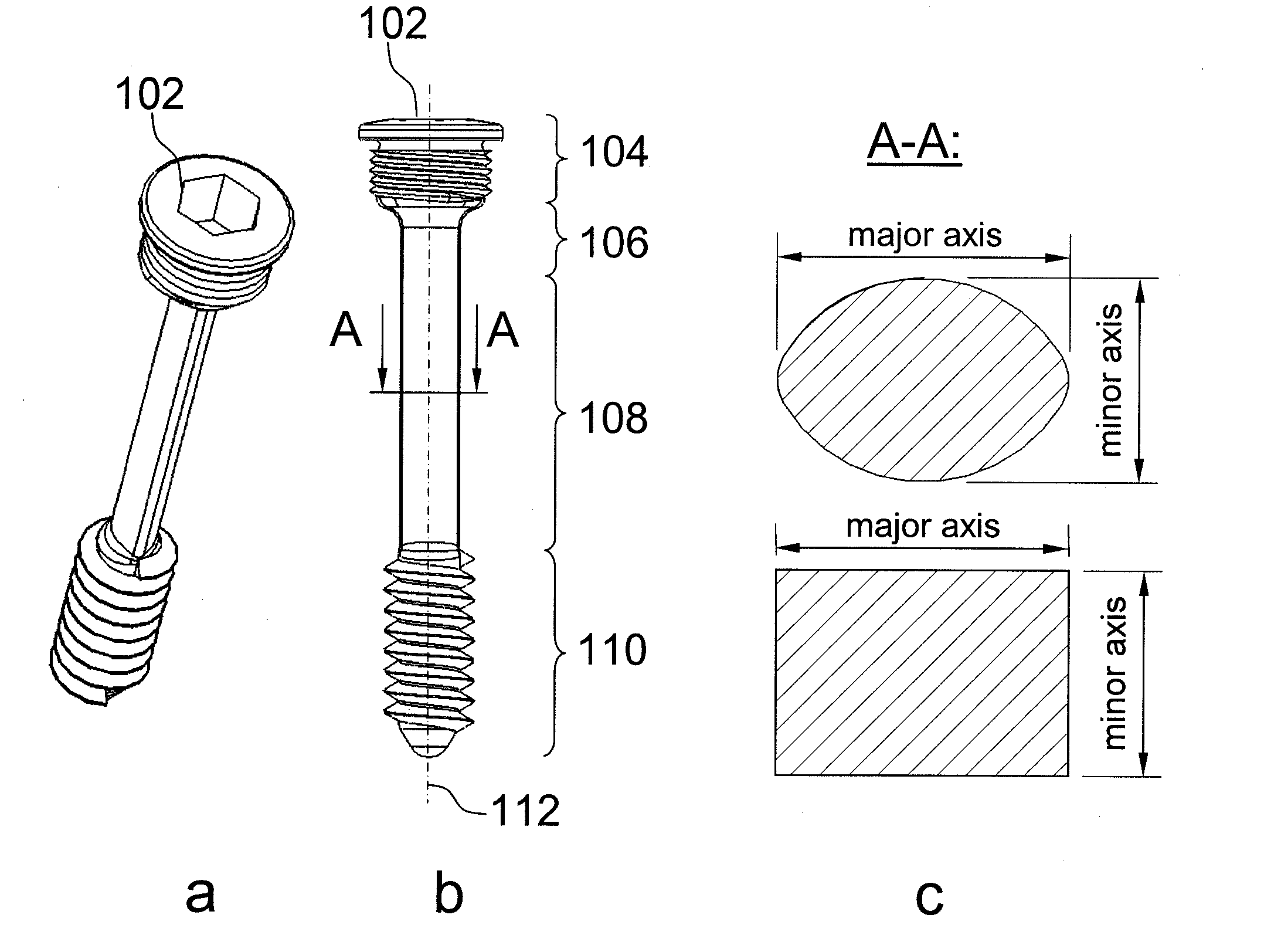
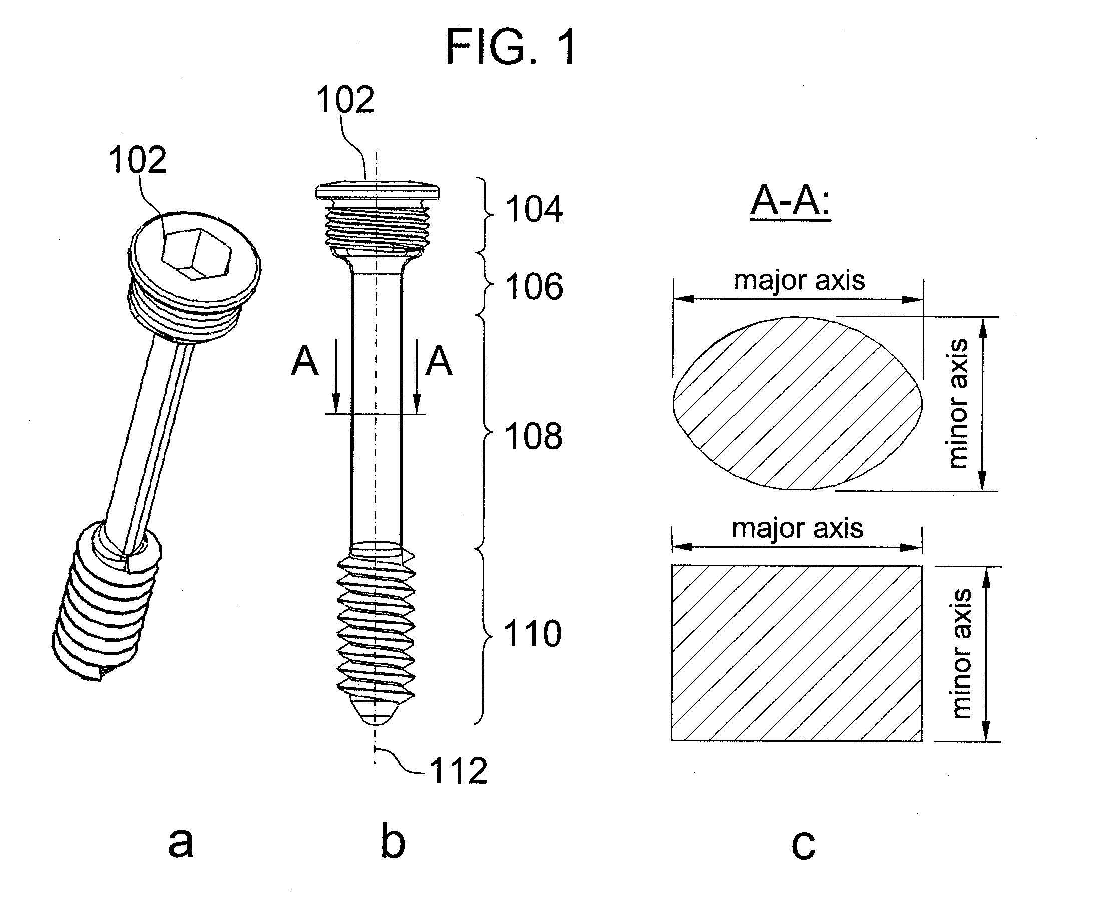
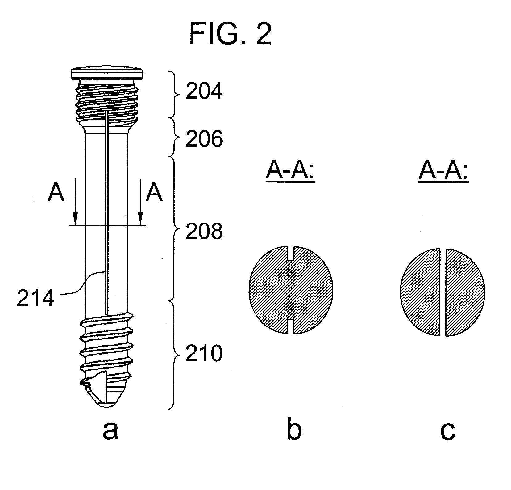
Embodiments of the present invention provide rotationally asymmetric bone screws. Embodiments of the present invention provide mechanisms that reduce the bending stiffness of conventional shaft bone screws in order to yield a less-rigid fixation construct. Such a less-rigid construct enables a controlled amount of motion at a fracture site which in turn promotes bone healing. As a means to reduce the bending stiffness of positive-locking bone screws, embodiments of the present invention provide a bone screw having a non-circular cross-section over parts of the screw length and / or longitudinal slots along at least a portion of the bone screw.

Description

TECHNICAL FIELD[0001]Embodiments of the present invention relate to the field of medical devices, and, more specifically, to a bone screw with features and / or attributes to provide positive-locking but flexible engagement to a bone.BACKGROUND[0002]Bone screws have typically been used to directly compress osteosynthesis plates onto a bone in order to align and stabilize a bone fracture. In this utilization, bone screws are not fixed rigidly to the bone plate, and the resulting frictional force between the plate and the bone is solely responsible for the stability of the osteosynthesis construct. Loosening of the screws in the bone or a resorption of the bone may thus easily lead to a loss of stability.[0003]To avoid such loosening, and for the purpose of improving vascularity in a manner that minimizes damage to the bone surface, means for rigid locking of bone screws in a bone plate and elevated fixation of a bone plate over the bone surface have been introduced. For example, in one...

Claims


Application Information

Patent Timeline
Patent Type & Authority Patents(United States)
IPC IPC(8): A61B17/56
CPCA61B17/8057A61B17/8625A61B17/863
Inventor BOTTLANG, MICHAELSOMMERS, MARK B.
Owner APEX BIOMEDICAL
Learn More