Suspension swing device

a swing device and suspension technology, applied in the direction of swings, rocking chairs, entertainment, etc., can solve the problems that the corresponding products of auto-swings and auto-cradles cannot be found in the market, and the auto-swing device cannot be used in different fields, so as to achieve simple structure, save energy, and operate silently

Inactive Publication Date: 2013-03-19
QIU BINGSHUN
View PDF4 Cites 3 Cited by
  • Summary
  • Abstract
  • Description
  • Claims
  • Application Information

AI Technical Summary

Benefits of technology

[0005]The invention solves the above problems that it provides a suspension swing device which is simple in structure, reliable, energy saving, silent in operation, easy to carry, and widely applied in different fields.
[0014]The present invention is advantageous in that the suspension swing device has simple structure, wherein the main components are only the gear motor and the microcomputer controller. The gear motor can directly drive the suspension frame to swing reciprocatingly through the torque output plate and the swing pushing member so as to enhance the reliability of the device without superfluous components. The swing of the suspension frame mainly relies on its inertia and the motor drive only occupies 5-20% of the swing cycle, to save electrical energy. No mechanical noise generated from the gear rotating and crankshaft connecting stem moving back and forth due to the impact thereof, so it can work silently. It has minimum components, small size, and light weight to be easily carried. It can be used in varieties of suspension swing drivers, such as swings, cradles, hammocks, so it can be widely used.

Problems solved by technology

However, the corresponding products of auto-swings and auto-cradles cannot be found in the market.
For example, China Patent ZL97199159.6 disclosed an auto-swing device which has complicated structure and is limited to the swing device such that the auto-swing device cannot be used in different fields.

Method used


Image

  • Suspension swing device
  • Suspension swing device
  • Suspension swing device

Examples


Embodiment Construction

[0027]In order to further know the advantages and features of the suspension swing device of the invention, two embodiments with their drawings are described in detail. But the suspension swing device is not limited to the embodiments.

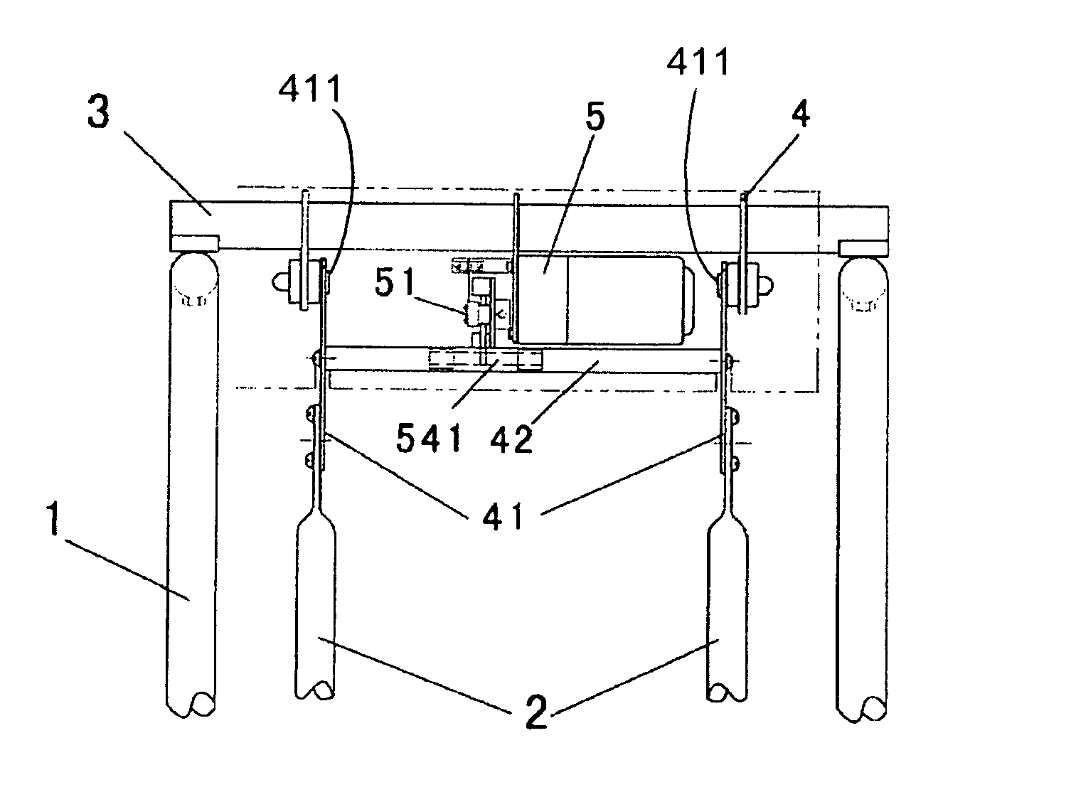
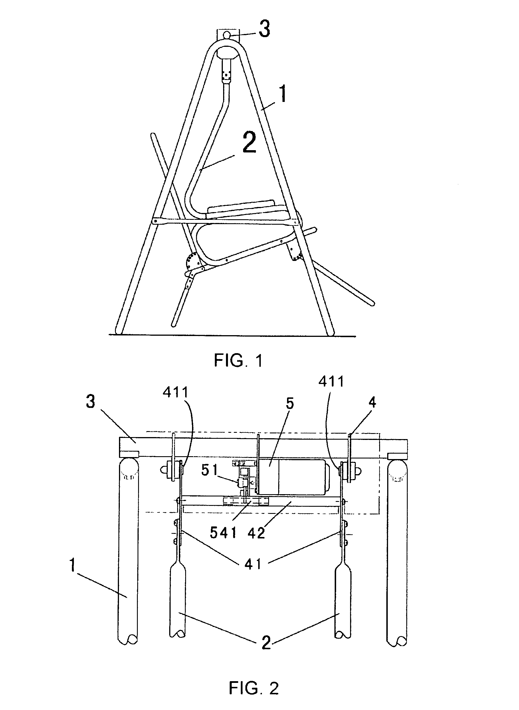
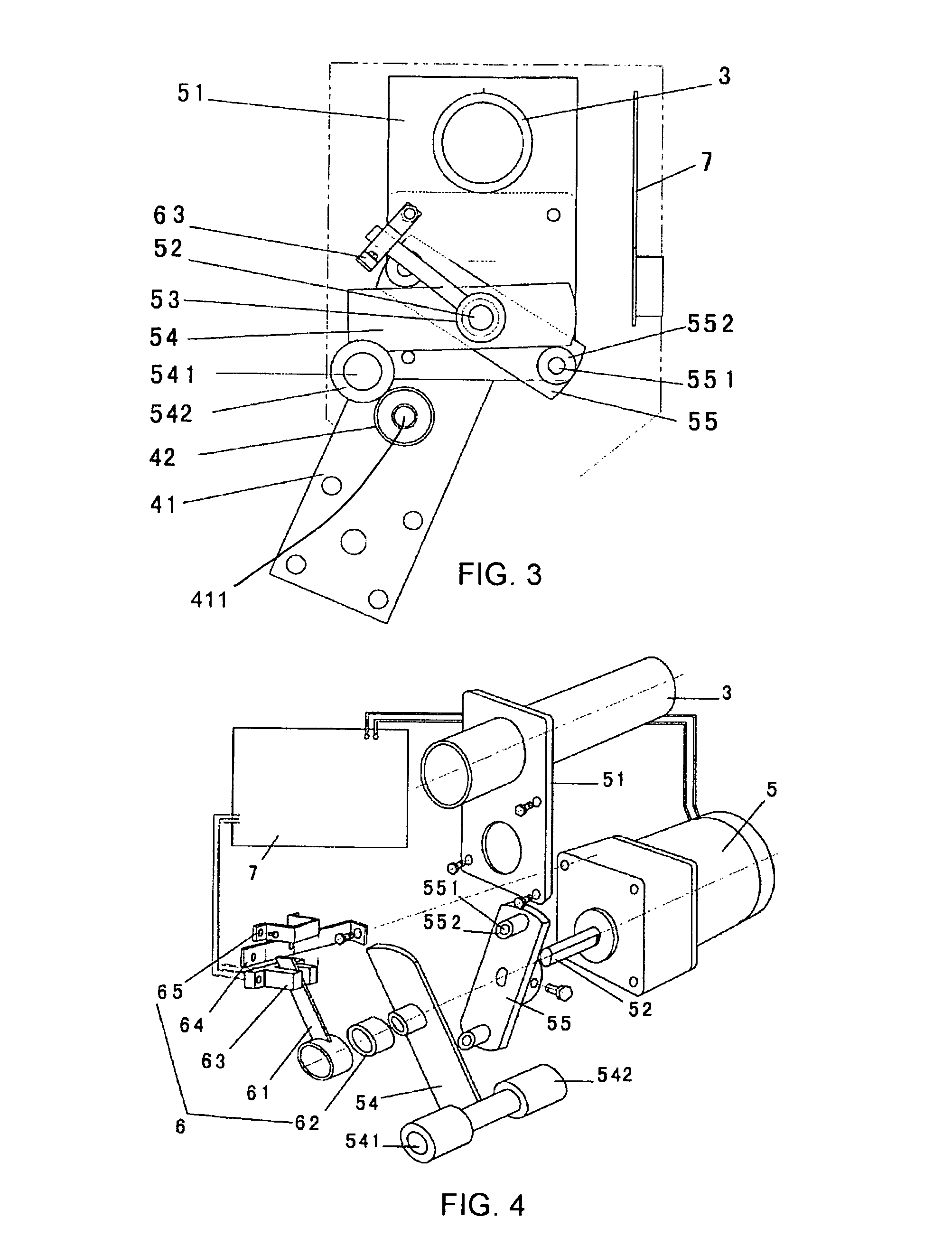
[0028]Referring to FIG. 1 to FIG. 7, and FIG. 10, a suspension swing device according to a first embodiment of the present invention is illustrated, wherein the suspension swing comprises a frame which comprises a supporting bracket 1, a suspension frame 2 for suspendedly supporting an object, a supporting beam 3, two suspended joints 4, a gear motor 5, a swing direction monitor 6, and a microcomputer controller 7. The supporting beam 3 is extended from the supporting bracket 1. The two suspended joint 4 are spacedly coupling at the supporting beam 3 for pivotally coupling with upper ends of the suspension frame 2. One end of a suspended swing stem 41 has a suspended swing shaft, wherein the suspended swing shaft is coupled with the bearings of the sus...


PUM


Abstract

A suspension swing device includes a supporting beam (3) of a supporting bracket (1), a suspended joint (4) fixed on the supporting beam (3) via bearings, a suspended swing stems (41), a gear motor (5), a torque output plate (55), a swing pushing member (54), a swing direction monitor (6) and a microcomputer controller (7). The suspended swing stem (41) is mechanically connected with the suspended joint (4). The gear motor (5) is mechanically connected with the supporting beam (3). The torque output plate (55) and the swing pushing member (54) are connected to the output shaft of the gear motor (5). The microcomputer controller (7) is connected with the swing direction monitor (6) and the gear motor (5). The on-off operation of the gear motor (5) is controlled by the microcomputer controller (7).

Description

BACKGROUND OF THE PRESENT INVENTION[0001]1. Field of Invention[0002]The present invention relates to a swing device, more particularly to a suspension swing electric device which can be used to swing, cradle, hammock, and other equipments which need automatic suspension swing device.[0003]2. Description of Related Arts[0004]Many China Patents teaching auto-swings and auto-cradles can be found in China Patent Literature Database. However, the corresponding products of auto-swings and auto-cradles cannot be found in the market. Accordingly, the auto-swings and auto-cradles have several drawbacks in order for mass production. For example, China Patent ZL97199159.6 disclosed an auto-swing device which has complicated structure and is limited to the swing device such that the auto-swing device cannot be used in different fields. Therefore, there is an improvement in the aspects of simple structure, reliability, energy saving, silent in operation, easy to carry, widely being applied in di...

Claims


Application Information

Patent Timeline
Patent Type & Authority Patents(United States)
IPC IPC(8): A63G9/16A63G9/00
CPCA47C3/0255A63G9/16A47C3/0251
Inventor QIU, BINGSHUN
Owner QIU BINGSHUN
Why Eureka
Try Eureka