
Method and system for operating a wind turbine

a wind turbine and wind power technology, applied in the direction of rotors, marine propulsion, vessel construction, etc., can solve the problems of price, lifetime and reliability, and achieve the effect of increasing the power production of the wind turbine and reducing the wear at the shaft bearing

Active Publication Date: 2013-03-19
GAMESA INNOVATION & TECH SA
View PDF2 Cites 20 Cited by
  • Summary
  • Abstract
  • Description
  • Claims
  • Application Information

AI Technical Summary

Benefits of technology

[0007]The object of the invention is to compensate for asymmetric load on the rotor in a wind turbine, a second object is to reduce wearing at shaft bearings in the wind turbine, and a third object is to increase the power production of a wind turbine.DESCRIPTION OF THE INVENTION
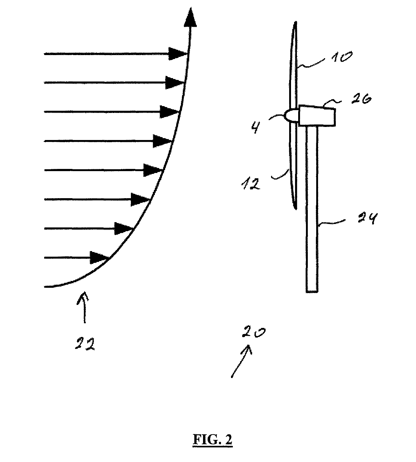
[0009]This can lead to an adjustment of the pitch of the blades. Where the load on the blades is minimum, the pitch angle is increased in order to achieve a higher load on the blade in order to adjust the asymmetric load to a minimum at the rotor. Further for the blade under high load, the pitch angle can be decreased for reducing the load. This adjustment into a symmetric load can by itself lead to an increasing power production. Due to the reduction of the bending on the shaft, the load on the bearings will also be reduced which can lead to an increasing lifetime of the main bearing in the wind turbine. In practice, the wind shear will be in the way where the load on the blades are maximum at the top and minimum at the lowest blade, but in actual life wind shear can be much more complicated. In normal situations, one single displacement sensor at the shaft could lead to a highly efficient regulation if the pitch regulation system is so fast operating that the pitch can be adjusted inside one single rotation of the rotor.
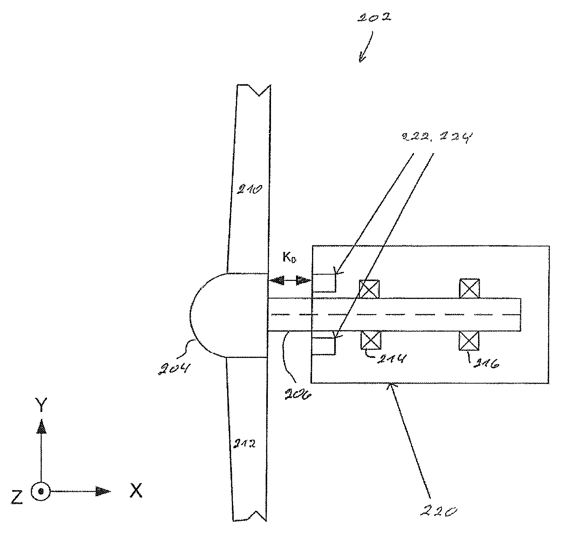
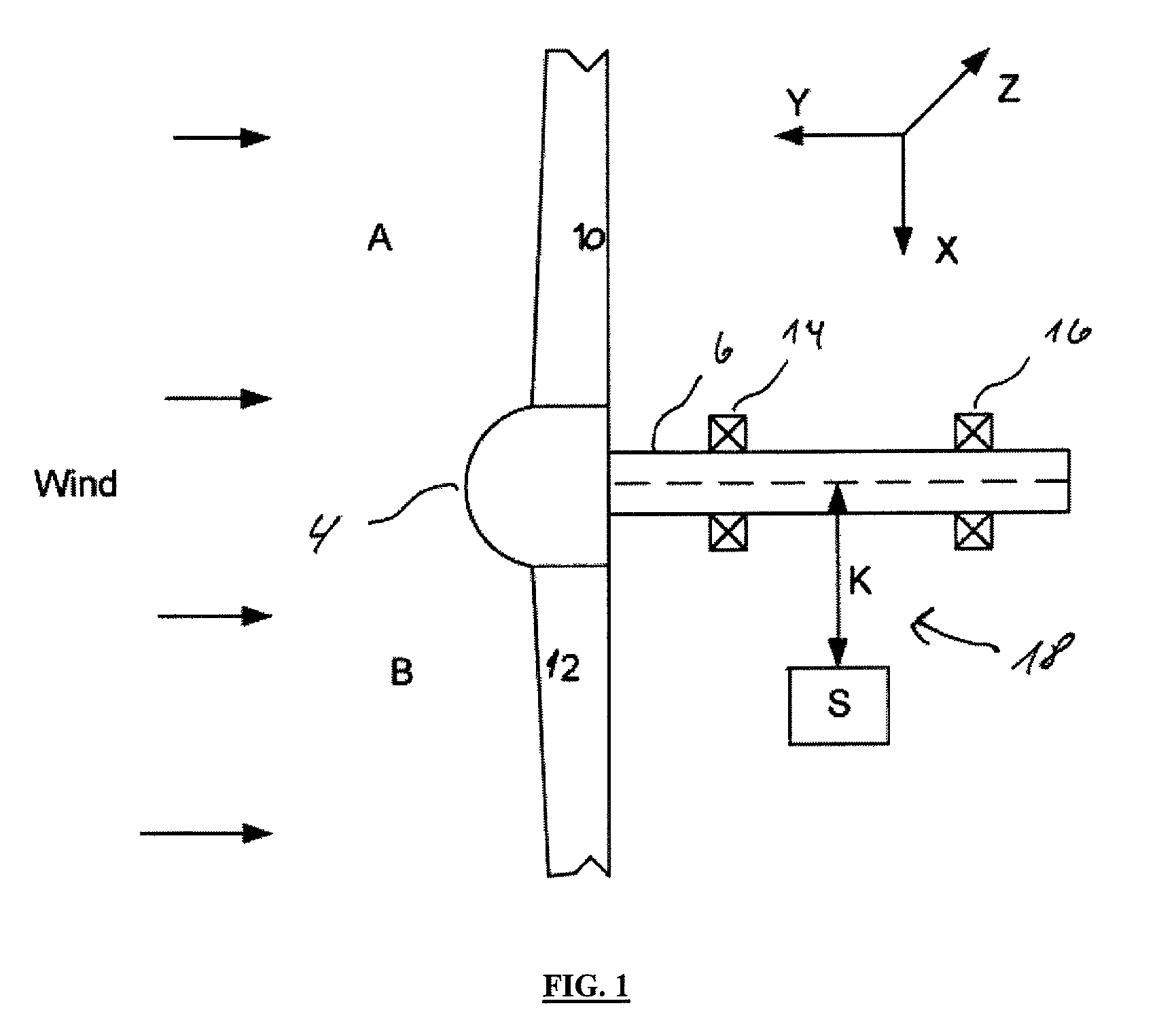
[0013]In a preferred embodiment for the invention, four displacement sensors are forming a group of sensors placed around the shaft. The lowest number of sensors which is required for describing displacement all around a circle of 360 degrees will probably be four, but a good picture could be achieved with only three sensors. By letting the sensors measure the surface of the shaft, it is possible by four detectors to indicate all displacement in two detectors where one of them will give a positive response and the other a negative response. Based on input from these four sensors, a computer system can give a good indication of the shaft bending, and clearly indicate the actual bending situation which can be used immediately for an adjustment of the pitch of the blades in order to bring the shaft bending close to zero.
[0018]The shaft in the WTR can be supported by at least a first bearing near the rotor and at least a second bearing at the other end of the shaft, which shaft has an unsupported section between the first and second bearings, where the displacement sensors are measuring the shaft bending at least at a position between the bearings. The unsupported section of the shaft will be very efficient for placing the sensors. Firstly the bending of the shaft is the highest between the bearings and for the secondly, that is a protected place in the wind turbine where detectors are protected from the environment simply because a shielding will typically be around the main shaft where these sensors can be placed under the shield.

Problems solved by technology

Disadvantages for all these systems are the price, lifetime and reliability.

Method used


Image

  • Method and system for operating a wind turbine
  • Method and system for operating a wind turbine
  • Method and system for operating a wind turbine

Examples


Embodiment Construction

[0008]This can be achieved with a method as described in the preamble to claim 1 if the method is modified so that the load regulation system measures the actual rotor load by at least one displacement sensor, which displacement sensor is measuring the bending of the main shaft, where the load regulation system based on the shaft bending regulates the individual pitch of the blades for compensating asymmetric load at the rotor.

[0009]This can lead to an adjustment of the pitch of the blades. Where the load on the blades is minimum, the pitch angle is increased in order to achieve a higher load on the blade in order to adjust the asymmetric load to a minimum at the rotor. Further for the blade under high load, the pitch angle can be decreased for reducing the load. This adjustment into a symmetric load can by itself lead to an increasing power production. Due to the reduction of the bending on the shaft, the load on the bearings will also be reduced which can lead to an increasing lif...


PUM


Abstract

The present invention relates to a method and a system for operating a Wind Turbine (WTG), which WTG comprises a rotor comprising at least two blades, which blades are pitch regulated, where the rotor is connected to a shaft, which shaft is supported by bearings, and which shaft drives at least one generator, where the WTG uses a load regulation system for regulating the individual pitch of at least two blades. The object of the invention is to compensate for asymmetric load on the rotor in a wind turbine, a second object is to reduce wearing at shaft bearings in the wind turbine, and a third object is to increase the power production of a wind turbine. This can be achieved if the load regulation system measures the actual rotor load by at least one displacement sensor, which displacement sensor is measuring the bending of the main shaft, where the load regulation system based on the shaft bending regulates the individual pitch of the blades for compensating asymmetric load at the rotor.

Description

FIELD OF THE INVENTION[0001]The present invention relates to a method for operating a Wind Turbine (WTG), which WTG comprises a rotor comprising at least two blades, which blades are pitch regulated, where the rotor is connected to a shaft, which shaft is supported by bearings, and which shaft is driving at least one generator, where the WTG uses a load regulation system for regulating the individual pitch of at least two blades.[0002]The present invention further relates to a system for pitch regulation of a Wind Turbine (WTG) comprising a rotor, which rotor comprises at least two blades, which rotor is connected to a shaft, which shaft is supported by at least a first bearing and a second bearing, which first bearing is carrying the rotor, where the second bearing supports the other end of the shaft, which shaft is further connected to a generator, which pitch regulation system regulates individual pitch of at least two blades.BACKGROUND OF THE INVENTION[0003]Wind turbines (WTG) a...

Claims


Application Information

Patent Timeline
Patent Type & Authority Patents(United States)
IPC IPC(8): F03D7/02F03D1/00
CPCF03D7/0224F03D7/024F03D7/0292F03D7/042F03D11/0091F05B2270/331F05B2270/404F05B2270/705F05B2270/821Y02E10/722Y02E10/723F03D17/00Y02E10/72
Inventor REBSDORF, ANDERSGLENT-MADSEN, HENRIK
Owner GAMESA INNOVATION & TECH SA
Learn More