Gait generating device of legged mobile robot
a mobile robot and gait generation technology, applied in the direction of electric programme control, program control, instruments, etc., can solve the problems that the external force necessary to achieve a desired motion cannot be applied to the robot, and the technique of generating the desired gait in the situation where external forces act on the robot, as described above, has not yet been fully studied, so as to achieve efficient and proper target determination
- Summary
- Abstract
- Description
- Claims
- Application Information
AI Technical Summary
Benefits of technology
Problems solved by technology
Method used
Image
Examples
first embodiment
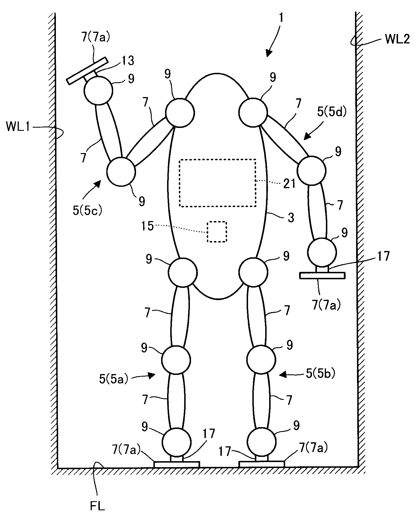
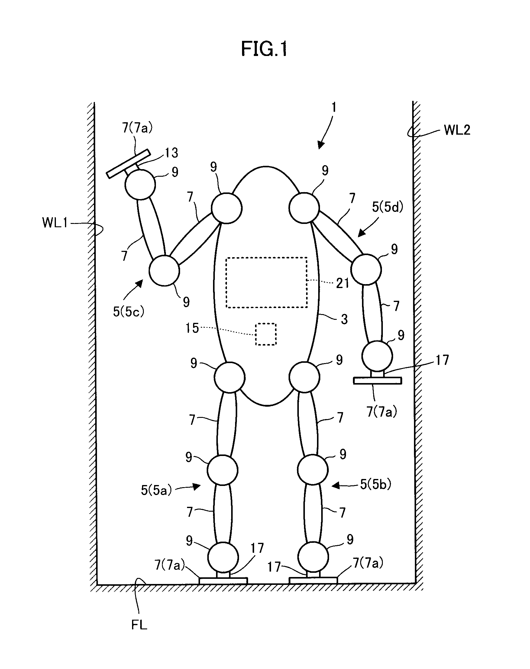
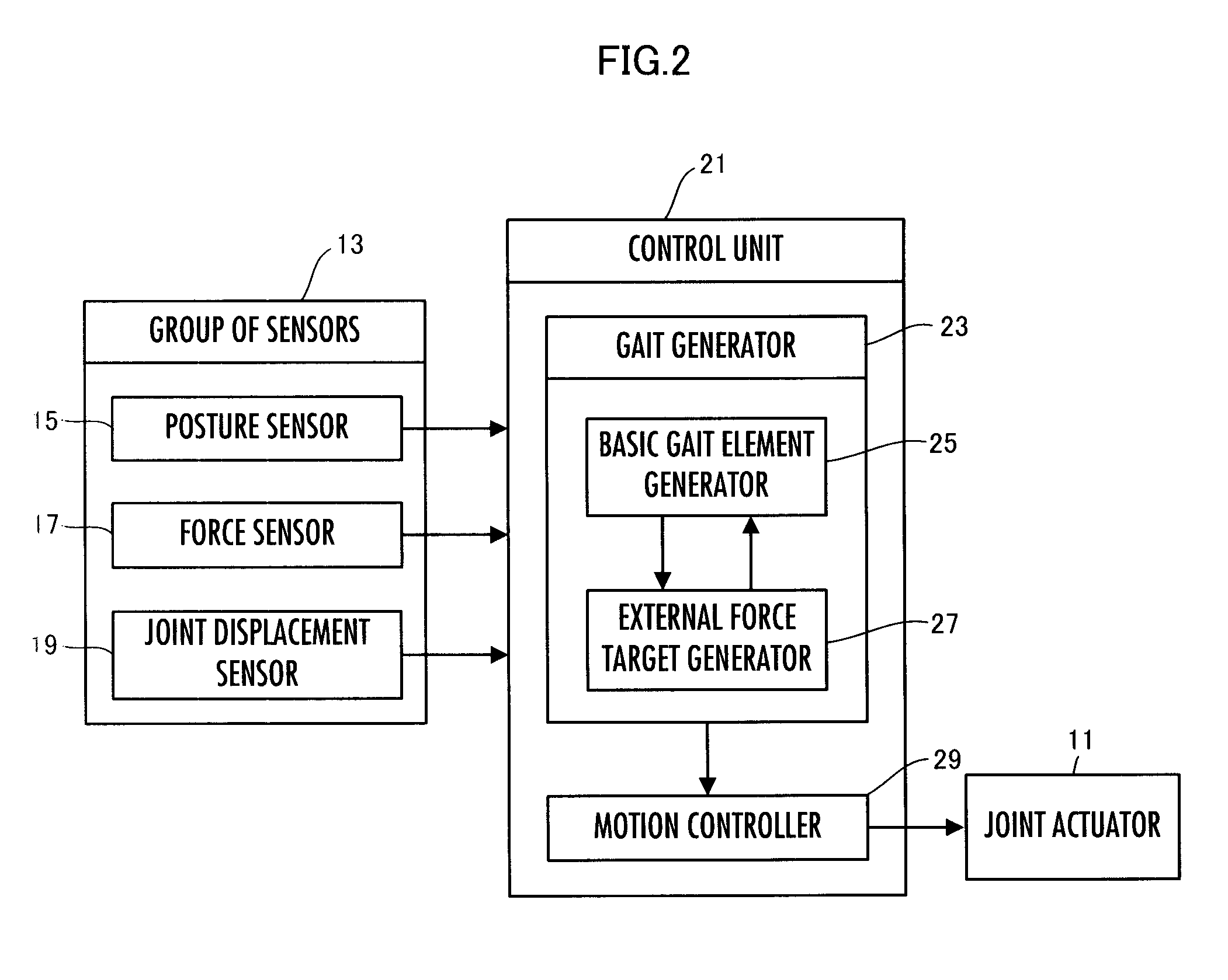
[0185]A first embodiment of the present invention will be described below with reference to FIG. 1 to FIG. 13.
[0186]Referring first to FIG. 1, the mechanical schematic construction of a legged mobile robot 1 in the present embodiment (hereinafter referred to simply as the robot 1) will be described.
[0187]This robot 1 has a body 3 and a plurality of link mechanisms 5 extended from the body 3. Each of the link mechanisms 5 is a mechanism capable of functioning as a leg of the robot 1. The quantity of the link mechanisms 5 is four in the present embodiment.
[0188]In the description of the present embodiment, the fact that the link mechanisms 5 are capable of functioning as the legs of the robot 1 means that the link mechanisms 5 are capable of receiving from a surface to be contacted an external force supporting all or a part of the self weight of the robot 1 (more accurately, the resultant force of the gravitational force acting on the robot 1 and the inertial force generated by a moti...
second embodiment
[0447]A second embodiment of the present invention will now be described with reference to FIG. 14 and FIG. 15. The present embodiment differs from the first embodiment only partly in the processing carried out by the external force target generator 27, so that the description of the same aspects as those of the first embodiment will be omitted.
[0448]In the first embodiment, the on-virtual-surface external force action point correction amount as the first compensation amount has been preferentially determined in the processing for determining the moment compensation amount for canceling the moment error errM (the processing in S21 to S37).
[0449]However, it is alternately possible to determine, for example, the virtual surface frictional force component correction amount f_i serving as the second compensation amount or the virtual surface twisting force R_i serving as the third compensation amount in preference to the on-virtual-surface external force action point correction amount. ...
third embodiment
[0505]The third embodiment of the present invention will now be described with reference to FIG. 16. The present embodiment differs from the first embodiment only partly in the processing by an external force target generator 27, so that the description of the same aspects as those of the first embodiment will be omitted.
[0506]If the surfaces to be contacted in an outside world of a robot 1 have two surfaces to be contacted that oppose each other with an interval provided therebetween, as with the aforesaid wall surfaces WL1 and WL2, and the virtual surface group set in S01 includes opposing virtual surfaces Sna and Snb, then the moment generated about a moment reference point can be changed by manipulating (increasing or decreasing) an internal force (=min (|N_na|, |N_nb|) between the opposing virtual surfaces Sna and Snb while maintaining the resultant force of the virtual surface normal force components N_na and N_nb in the opposing virtual surfaces Sna and Snb constant. Hence, t...
PUM
 Abstract
Description
Claims
Application Information
 - R&D
- Intellectual Property
- Life Sciences
- Materials
- Tech Scout
- Unparalleled Data Quality
- Higher Quality Content
- 60% Fewer Hallucinations
Browse by: Latest US Patents, China's latest patents, Technical Efficacy Thesaurus, Application Domain, Technology Topic, Popular Technical Reports.
© 2025 PatSnap. All rights reserved.Legal|Privacy policy|Modern Slavery Act Transparency Statement|Sitemap|About US| Contact US: help@patsnap.com


