
Method for encapsulating the edge of a flexible sheet

a flexible sheet and edge technology, applied in the direction of photovoltaic supports, solid-state devices, coatings, etc., can solve the problems of reducing surface area efficiency, difficult to bond injection moldable materials to the top surface, and compounding difficulty

Inactive Publication Date: 2013-02-19
DOW GLOBAL TECH LLC
View PDF25 Cites 12 Cited by
  • Summary
  • Abstract
  • Description
  • Claims
  • Application Information

AI Technical Summary

Benefits of technology

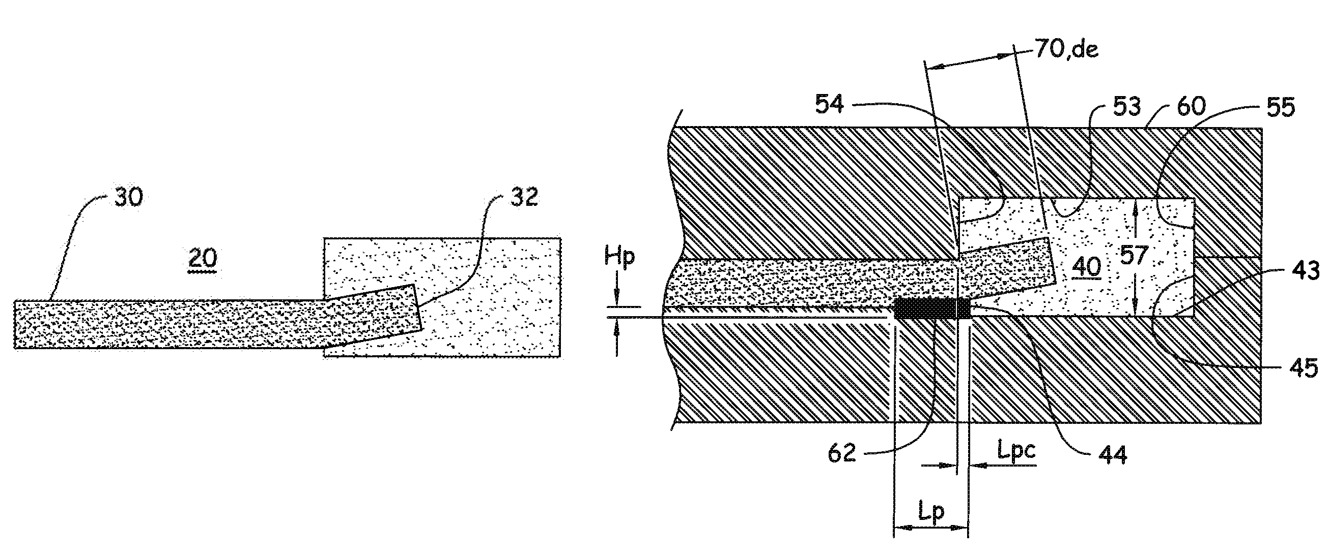
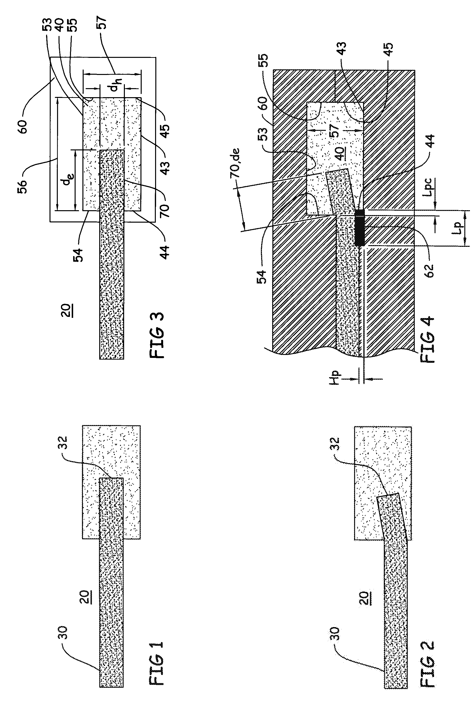
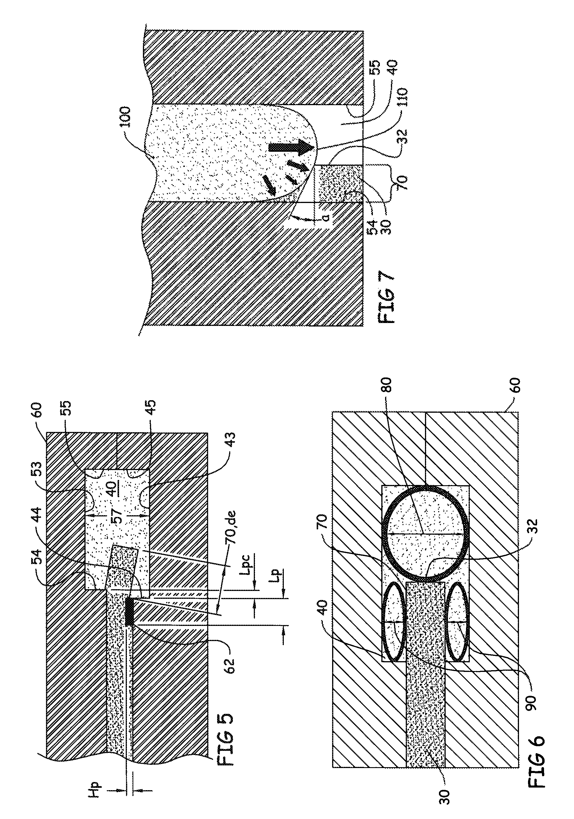
The present invention describes a method of encapsulating both sides of the edge of a flexible laminate or sheet using the injection molding process. This method results in minimal force imbalances between the opposing sides of the flexible article, resulting in polymer on both sides. This can be achieved without using rigid pins or structures firmly holding the flexible article as are common in the industry. The technical effect of this invention is the ability to efficiently and effectively encapsulate flexible laminates or sheets using injection molding techniques.

Problems solved by technology

Combining these features and the traits previously mentioned, into a device presents challenge.
This process has its own challenges in working with the PV cell systems (laminates) common to solar.
The desired small area for the inactive area presents challenges with adhesion and attachment to the laminate structure.
This difficulty is compounded further in the case of a flexible laminate mimicking a traditional flexible shingle.
These same anti-fouling traits make it very difficult to bond an injection moldable material to the top surface.
This also results in reduction of surface area efficiency due to adding of tie-layers and their tolerances.
The problem is to develop an over-molding process that places thermoplastic on both sides of a laminated PV cell assembly, in order to seal and protect the cell edges, (does not force the laminate to the edge of the mold) and does not require the use of pins or guides to suspend the laminate in the center of the tool cavity.

Method used


Image

  • Method for encapsulating the edge of a flexible sheet
  • Method for encapsulating the edge of a flexible sheet
  • Method for encapsulating the edge of a flexible sheet

Examples


example

[0040]As one non-limiting example of the inventive method, the following steps are contemplated:

[0041]A method of producing an over-molded article may include the steps of: a) providing a substrate to be over-molded, wherein the substrate has a Young's modulus of 150 MPa to 1500 MPa (10,000 psi to 10 MM psi with a preferred range of 400M psi to 500 Mpsi), has an upper surface, lower surface, and a side surface connecting the upper and lower surface, and a centerline equidistant from the upper and lower surfaces; b) providing a mold with a mold cavity including a first and a second section defining a cavity, the mold cavity having an upper wall, a lower wall and an inner and outer side wall interconnected therebetween, a cavity height defined by the distance between the upper wall and the lower wall, wherein the mold is essentially void of any nesting device inside the mold cavity to support the substrate; c) placing and aligning an edge of the substrate onto the first section of the...


PUM

PropertyMeasurementUnit
Young's modulusaaaaaaaaaa
thickness dhaaaaaaaaaa
distanceaaaaaaaaaa

Abstract

The present invention is premised upon an inventive method of producing an over-molded edge portion on a flexible substrate, wherein the edge portion is void of open areas due to support devices in the mold cavity.

Description

CLAIM OF BENEFIT OF FILING DATE[0001]The present application claims the benefit of the filing date of PCT Application Serial No. PCT / US2009 / 042507 (filed May 1, 2009) (Published as WO 2009 / 137351); and U.S. Provisional Application Ser. No. 61 / 050,341 (filed May 5, 2008), the contents of which are hereby incorporated by reference in their entirety.[0002]This invention was made with U.S. Government support under contract DE-FC36-07G017054 awarded by the Department of Energy. The U.S. Government has certain rights in this invention.FIELD OF THE INVENTION[0003]The present invention relates to an improved method for encapsulating the edge of a flexible sheet, more particularly by encapsulating a flexible sheet via an over molding process.BACKGROUND[0004]Generally, efforts to improve the encapsulation of edges of flexible sheets have taken many forms over the years. One type of flexible sheet that is of particular interest is photovoltaic cell assemblies. These photovoltaic (“PV”) cell as...

Claims


Application Information

Patent Timeline
Patent Type & Authority Patents(United States)
IPC IPC(8): B29C45/14
CPCB29C45/14336B29C45/14778H01L21/565H01L31/048H02S20/00B29C45/0046B29C45/14377H01L2924/0002Y02E10/50H01L2924/00H02S30/10
Inventor KEENIHAN, JAMES R.CLAREY, TODD M.
Owner DOW GLOBAL TECH LLC
Learn More