
Connection system for mounting a device onto a support arm

a technology for connecting systems and support arms, which is applied in the field of system for attaching and detaching devices to and from support arms, can solve problems such as user injury and imbalanced support arms, and achieve the effect of reducing weight loss and safe and quick attachment and detachment of devices

Active Publication Date: 2011-05-12
AMERICAN STERILIZER CO
View PDF11 Cites 20 Cited by
  • Summary
  • Abstract
  • Description
  • Claims
  • Application Information

AI Technical Summary

Benefits of technology

[0007]An advantage of the present invention is a connection system that allows for the safe and quick attachment and detachment of a device to and from a support arm.
[0008]Another advantage of the present invention is a connection system as described above that compensates for an imbalance in force when a device is removed from a support arm.
[0009]Another advantage of the present invention is a connection system as described above that allows a single user to safely and quickly attach and detach a device to and from a support arm.
[0010]Another advantage of the present invention is a connection system as described above that allows for the safe removal of a device from a spring-loaded support arm.
[0011]Another advantage of the present invention is a connection system as described above that attaches a weighted key member onto a support arm to offset the weight lost when a device is detached from the support arm.
[0012]Another advantage of the present invention is a connection system as described above that secures a device onto a support arm.

Problems solved by technology

However, when the camera is removed from the support arm, the loaded springs cause the support arm to become imbalanced.
As a result of the imbalance, the end of the support arm will recoil rapidly, which can potentially cause injury to a user.

Method used


Image

  • Connection system for mounting a device onto a support arm
  • Connection system for mounting a device onto a support arm
  • Connection system for mounting a device onto a support arm

Examples


Embodiment Construction

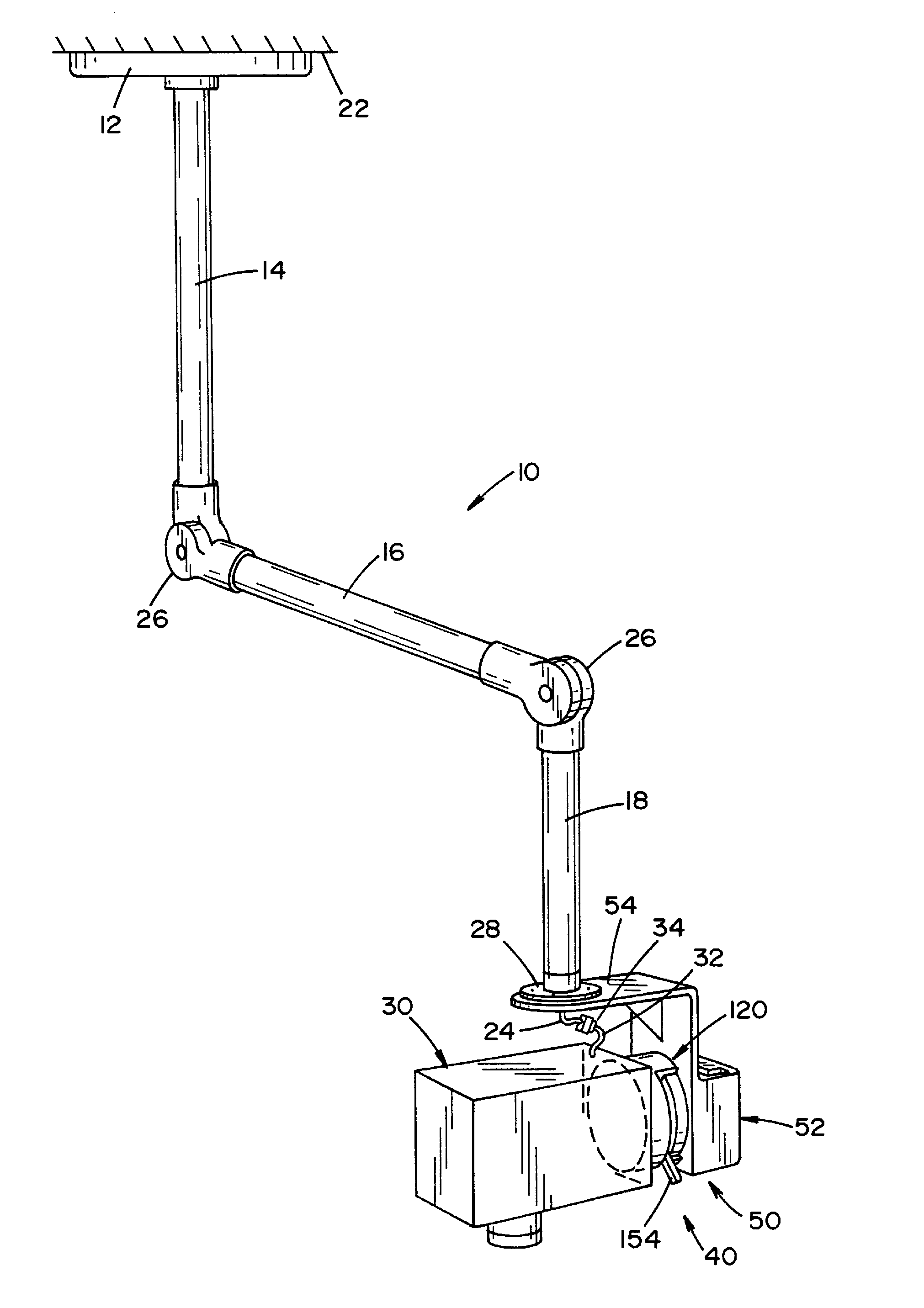
[0035]Referring now to the drawings wherein the showings are for the purpose of illustrating a preferred embodiment of the invention only, and not for the purpose of limiting same, FIG. 1 shows a ceiling-mounted, articulating arm 10 supporting a medical device 30. In the embodiment shown, device 30 is a camera used in surgical operating rooms.

[0036]As best seen in FIGS. 1 and 2, arm 10 includes a mounting plate 12, a vertical arm member 14, an intermediate arm member 16 and a lower arm member 18. Mounting plate 12 is attached to a ceiling 22. A vertical arm member 14 is attached to mounting plate 12. Intermediate arm member 16 is connected to vertical arm member 14 and lower arm member 18 by articulating joints 26. Vertical arm member 14, intermediate arm member 16 and lower arm member 18 are tubular in shape and define an inner passage (not shown) through which data carrying cables and wires 24 are arranged. Springs (not shown) are disposed in the inner passage of vertical arm memb...


PUM


Abstract

The present invention provides a connection system for attaching and detaching a device to and from a support arm. The connection system is comprised of a key member having a keyed portion. A first section is attachable to a support arm. The first section is dimensioned to receive the keyed portion of the key member. A second section is attachable to a device. The second section is dimensioned to attach to the first section. An actuator is operable to move between a first position and a second position. The second section is locked to the first section when the actuator is in the first position. The second section is detachable from the first section when the key member is locked to the first section and the actuator is in the second position.

Description

FIELD OF THE INVENTION[0001]The present invention relates generally to a ceiling-mounted, surgical camera system for use in a surgical theater, and more particularly, to a system for attaching and detaching a device to and from a support arm. The present invention is particularly applicable to a connection system for attaching and detaching a camera to and from a spring-loaded support arm of a ceiling-mounted, surgical camera system and will be described with particular reference thereto. It being appreciated, however, that the present invention finds advantageous application in other types of apparatus wherein a device is attached and detached from a support arm.BACKGROUND OF THE INVENTION[0002]Cameras are used in surgical and operating rooms to take images of an operation site during a surgical procedure. The images taken by the camera may be displayed on video monitors, recorded for training purposes or transmitted to remote sites.[0003]The camera typically is attached to a ceili...

Claims


Application Information

Patent Timeline
Patent Type & Authority Applications(United States)
IPC IPC(8): A47B96/06
CPCF16M11/04F16M11/041F16M11/08F16M11/12F16M2200/066F16M11/2064F16M13/02F16M2200/02F16M2200/065F16M11/18
Inventor DORRIS, JEFFREY K.WILLIAMS, ALAN R.
Owner AMERICAN STERILIZER CO
Learn More