
MRI-guided medical interventional systems and methods

a technology of medical intervention and guided medical, applied in the field of in vivo medical systems and methods, can solve the problems of reduced efficacy, long duration of procedures, and less than optimal clinical efficacy of devices/procedures, and achieve the effect of preventing over-extension of cables or unwanted adjustments

Active Publication Date: 2013-02-12
CLEARPOINT NEURO INC
View PDF122 Cites 92 Cited by
  • Summary
  • Abstract
  • Description
  • Claims
  • Application Information

AI Technical Summary

Benefits of technology

[0016]In some embodiments, the actuators are color-coded such that each different actuator has a respective different color. This allows a user to quickly determine which actuator is the correct one for a particular desired movement of the frame.
[0021]In some embodiments, each control cable has a geometrically shaped rigid end that is configured to removably engage a free end of a respective actuator. Each control cable rigid end may have a shape that is different from the other control cable rigid ends such that each control cable free end can only removably engage one of the respective actuator free ends. Each control cable includes a flexible elastomeric collar that is configured to surround a respective actuator free end and to maintain engagement of a cable end to a respective actuator free end. Each flexible collar can be rolled or folded back then released to cover and conformably compress against an actuator free end to hold the end of the cable in position; then the collar can be pushed back to easily release the cable from an actuator free end.
[0022]According to some embodiments, a safety lanyard may be used to connect the remote control module to a rigid object, such as a patient support frame or head coil (or even the gantry or gantry housing) to prevent over extension of the cables or unwanted adjustments to the trajectory.
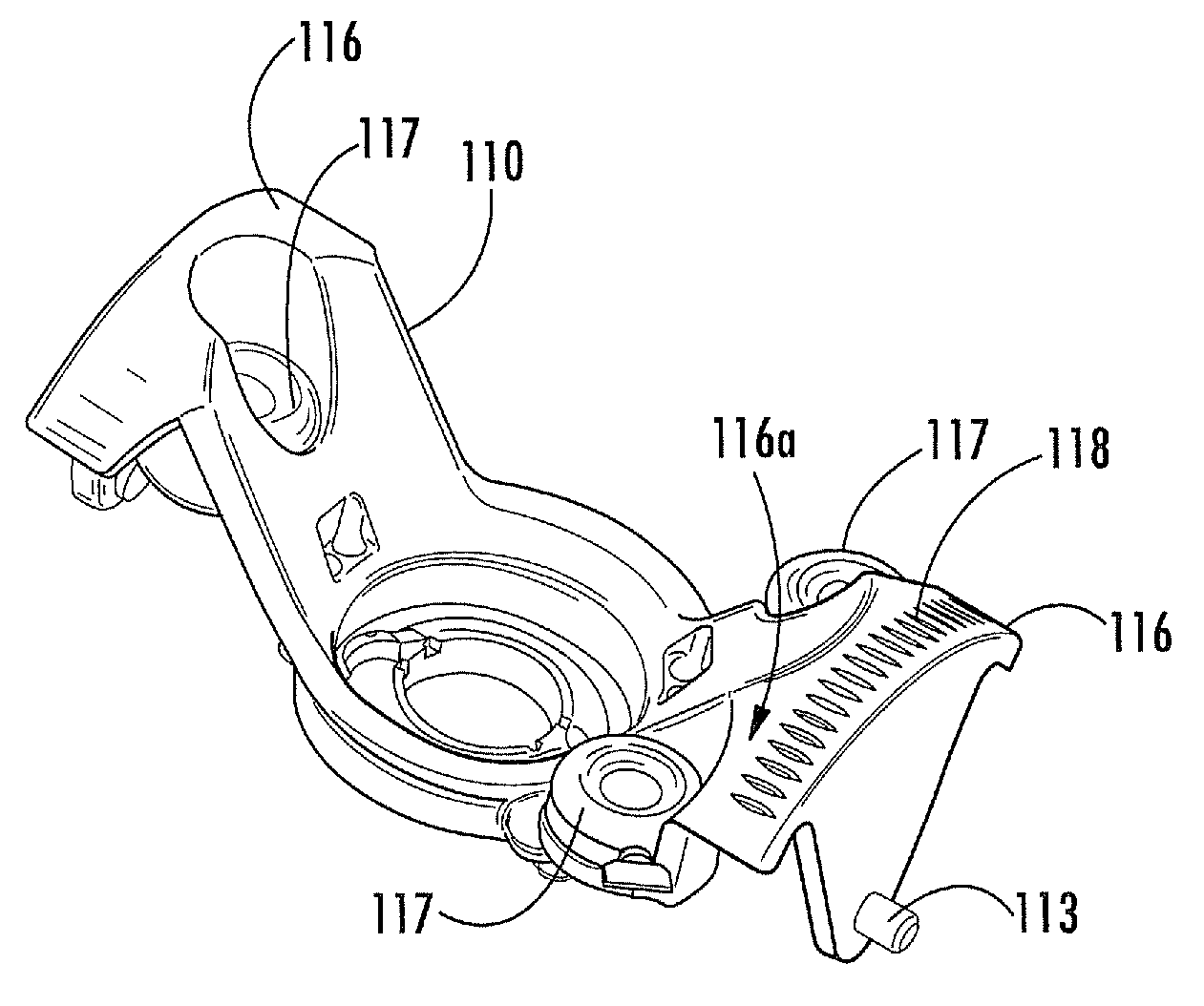
[0031]According to some embodiments, an MRI-guided interventional system for use with a body of patient and an interventional device includes a base and a targeting cannula. The base is configured to be secured to the body of the patient. The targeting cannula has an elongate guide bore extending axially therethrough and an inlet and an outlet at opposed ends of the guide bore. The guide bore defines a trajectory axis extending through the inlet and the outlet and being configured to guide placement of the interventional device. The frame is operable to move the targeting cannula relative to the base to position the trajectory axis to a desired intrabody trajectory to guide placement of the interventional device in vivo. The inlet tapers from an outer diameter distal from the guide bore to an inner diameter proximate the guide bore to guide and facilitate insertion of the interventional device into the guide bore.
[0053]According to some embodiments, a trajectory guide frame for guiding an interventional device with respect to a body of a patient in an MRI-guided procedure includes a base, a targeting cannula and a plurality of MRI-visible fiducial markers. The base has a patient access aperture therein. The base is configured to be secured to the body of a patient. The targeting cannula is mounted on the base for movement relative thereto. The targeting cannula includes a guide bore therethrough that is configured to guide placement of the interventional device in vivo. The plurality of MRI-visible fiducial markers are mounted on the base. The MRI-visible fiducial markers are relatively positioned in an asymmetric layout to facilitate positive determination of an orientation of the base in free space from an MR image.

Problems solved by technology

These procedures can be long in duration and may have reduced efficacy as it has been reported that, in about 30% of the patients implanted with these devices, the clinical efficacy of the device / procedure is less than optimum.

Method used


Image

  • MRI-guided medical interventional systems and methods
  • MRI-guided medical interventional systems and methods
  • MRI-guided medical interventional systems and methods

Examples


Embodiment Construction

[0116]The present invention now is described more fully hereinafter with reference to the accompanying drawings, in which some embodiments of the invention are shown. This invention may, however, be embodied in many different forms and should not be construed as limited to the embodiments set forth herein; rather, these embodiments are provided so that this disclosure will be thorough and complete, and will fully convey the scope of the invention to those skilled in the art.

[0117]Like numbers refer to like elements throughout. In the figures, the thickness of certain lines, layers, components, elements or features may be exaggerated for clarity.

[0118]The terminology used herein is for the purpose of describing particular embodiments only and is not intended to be limiting of the invention. As used herein, the singular forms “a”, “an” and “the” are intended to include the plural forms as well, unless the context clearly indicates otherwise. It will be further understood that the term...


PUM


Abstract

An MRI-guided interventional system for use with a body of patient and an interventional device includes a base and a targeting cannula. The base is configured to be secured to the body of the patient. The targeting cannula has an elongate guide bore extending axially therethrough and an inlet and an outlet at opposed ends of the guide bore. The guide bore defines a trajectory axis extending through the inlet and the outlet and being configured to guide placement of the interventional device. The frame is operable to move the targeting cannula relative to the base to position the trajectory axis to a desired intrabody trajectory to guide placement of the interventional device in vivo. The inlet tapers from an outer diameter distal from the guide bore to an inner diameter proximate the guide bore to guide and facilitate insertion of the interventional device into the guide bore.

Description

RELATED APPLICATIONS[0001]This application is a continuation-in-part application of U.S. patent application Ser. No. 12 / 134,412, filed Jun. 6, 2008, now U.S. Pat. No. 8,175,677 which claims the benefit of and priority to U.S. Provisional Patent Application No. 60 / 933,641, filed Jun. 7, 2007, and to U.S. Provisional Patent Application No. 60 / 974,821, filed Sep. 24, 2007, the disclosures of which are incorporated herein by reference as if set forth in their entireties.FIELD OF THE INVENTION[0002]The present invention relates generally to medical systems and methods and, more particularly, to in vivo medical systems and methods.BACKGROUND OF THE INVENTION[0003]Deep Brain Stimulation (DBS) is becoming an acceptable therapeutic modality in neurosurgical treatment of patients suffering from chronic pain, Parkinson's disease or seizure, and other medical conditions. Other electro-stimulation therapies have also been carried out or proposed using internal stimulation of the sympathetic nerv...

Claims


Application Information

Patent Timeline
Patent Type & Authority Patents(United States)
IPC IPC(8): A61B5/055
CPCA61N1/0534G01R33/286G01R33/287G01R33/3415A61B5/004A61B5/0042A61B5/0044A61B5/055A61B5/062A61B5/4836A61B5/4839A61B18/00A61N1/0529A61B19/201A61B5/0555A61B19/203A61B19/26A61B19/50A61B19/5212A61B19/5225A61B19/56A61B2017/00212A61B2017/00477A61B2017/00911A61B2017/3407A61B2017/3409A61B2019/208A61B2019/2269A61B2019/501A61B2019/507A61B2019/5206A61B2019/5217A61B2019/5231A61B2019/5236A61B2019/5433A61B2019/5437A61B2019/545A61B2019/5454A61B2019/5483A61B2019/562A61B2019/566A61N1/36014A61N1/372A61B2090/103A61B2090/3983A61B2034/101A61B2090/373A61B2034/256A61B2090/3614A61B34/25A61B90/361A61B90/50A61B90/11A61B90/14A61B34/74A61B34/10A61B2034/107A61B2090/306A61B90/37A61B2090/374A61B2090/3933A61B2090/3937A61B2090/395A61B2090/3954A61B2034/252A61B5/0036
Inventor PIFERI, PETERSAYLER, DAVID JOHNJENKINS, KIMBLE
Owner CLEARPOINT NEURO INC
Learn More