
Miter box with adjustable clamps

a technology of adjustable clamps and miter boxes, which is applied in the field of miter boxes, can solve the problems of complicated use and high manufacturing cost of miter boxes

Inactive Publication Date: 2013-02-12
MERIDIAN INT +1
View PDF15 Cites 2 Cited by
  • Summary
  • Abstract
  • Description
  • Claims
  • Application Information

AI Technical Summary

Benefits of technology

Enables secure and precise cutting of angles by stabilizing the miter box and work piece, reducing user effort and preventing movement during cutting, while maintaining ease of use and cost-effectiveness.

Problems solved by technology

Attempts to solve this problem have resulted in miter boxes that are expensive to manufacture and complicated to use.

Method used


Image

  • Miter box with adjustable clamps
  • Miter box with adjustable clamps
  • Miter box with adjustable clamps

Examples


Embodiment Construction

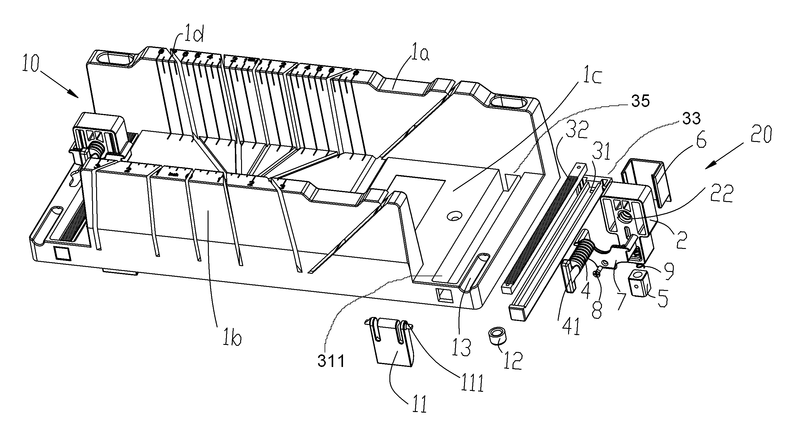
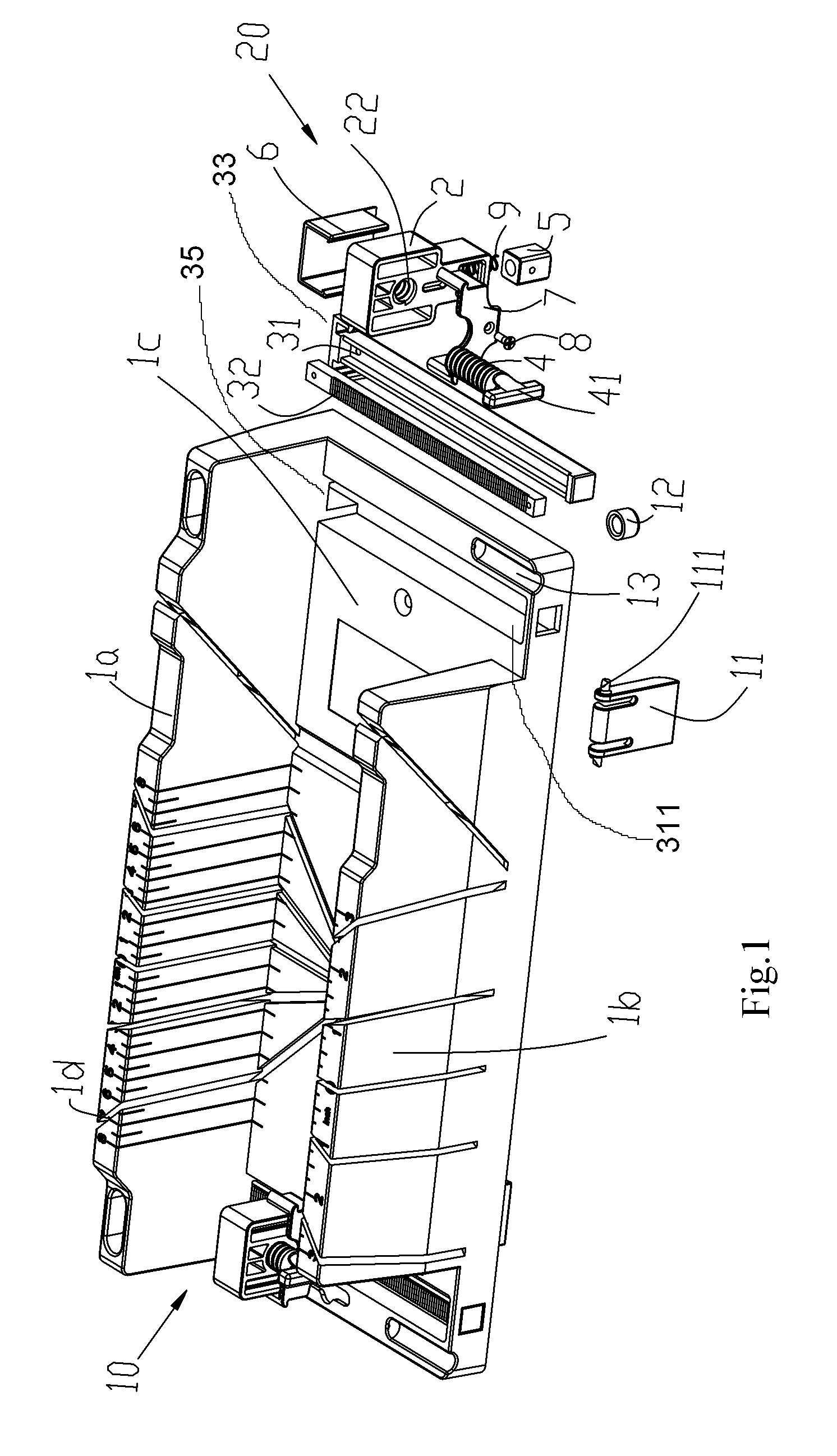
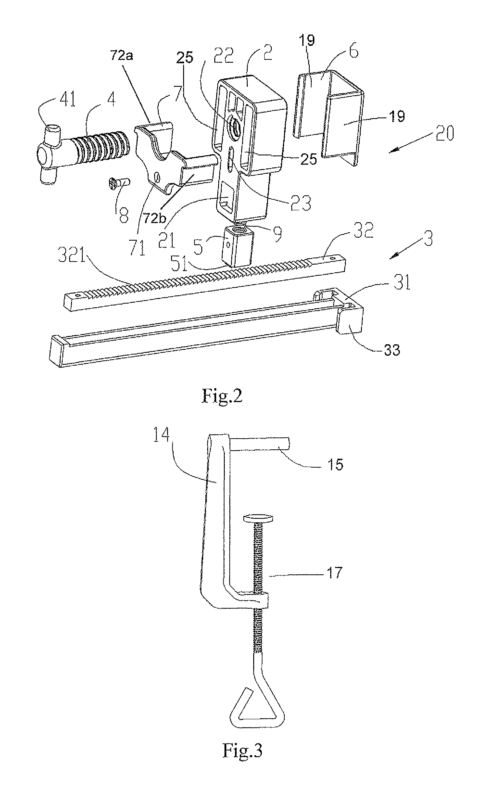
[0007]Referring to FIG. 1 is an illustration of an embodiment of the invention. The miter box 10 comprises an elongated base 1c with opposed side walls 1a and 1b. The miter box has at least one and preferably six aligned slots 1d cut into each side wall so that a saw is guided into position and held in the position while cutting. This allows the user to quickly and accurately cut angles including 90, 45, and 22.5 degrees. The top face of side walls 1a and 1b may have measurement marks which also aide the user in measuring the work piece for cutting.

[0008]In an embodiment, the miter box may also have one or more bracing legs 11 in alignment on the under side of the miter box 10. Miter box 10 is formed to have a receptacle for pivot pin 111. Pivot pin 1111 attaches the leg 11 to miter box 10. This allows the user to pivot the legs 11 down and place the miter box 10 against the end of a table. The legs 11 brace miter box 10 against the table preventing the miter box 10 from sliding for...


PUM

PropertyMeasurementUnit
cut anglesaaaaaaaaaa

Abstract

The present invention relates to a miter box. Miter boxes have a base, a pair of opposed side walls, and at least one aligned slot in the side walls. An embodiment of the present invention includes at least one guide rail mounted on the base perpendicular to the side wall. Further, a clamping assembly is positioned on the guide rail. The clamping assembly is selectively moveable along said guide rail. In this manner, a work piece can be secured to the miter box to hold the piece in position while it is being cut.

Description

CROSS-REFERENCE TO RELATED APPLICATIONS[0001]The present application claims priority under 35 USC §119 to Chinese application 200820057550.7 filed Apr. 22, 2008, which is incorporated herein by reference.BACKGROUND[0002]Miter boxes have been in use for many years. Miter boxes are used for cutting pieces of wood at a pre-determined angle. The miter box has aligned slots in the side walls to allow the user to position the saw. The slots prevent the saw from moving or shifting away from position. When using the miter box the user must use one hand to hold the work piece and the miter box while using the other hand to cut. As a result often the work piece will move or the miter box will slide across the table. Attempts to solve this problem have resulted in miter boxes that are expensive to manufacture and complicated to use.SUMMARY OF THE INVENTION[0003]The present invention relates to a miter box. Miter boxes have a base, a pair of opposed side walls, and at least one aligned slot in ...

Claims


Application Information

Patent Timeline
Patent Type & Authority Patents(United States)
IPC IPC(8): B26D7/01B26D7/26
CPCB27G5/026Y10T83/8773Y10T83/695Y10T83/76
Inventor ZHANG, YU JUN
Owner MERIDIAN INT
Learn More