
Wrench equipped with a precise torque-measuring device

a torque-measuring device and wrench technology, applied in the field of wrenches, can solve the problems of poor precision in setting the torque value of the unit's digit, and the problem is particularly serious

Active Publication Date: 2013-02-12
MATATAKITOYO TOOL
View PDF6 Cites 13 Cited by
  • Summary
  • Abstract
  • Description
  • Claims
  • Application Information

AI Technical Summary

Benefits of technology

[0007]It is the primary objective of the present invention to provide a wrench that shows values of torque precisely.

Problems solved by technology

Secondly, the precision in setting a digit in the ten's or hundred's place of a value of torque is acceptable; however, the precision in setting a digit in the unit's place of the value of torque is poor.
This problem is particularly serious with U.S. Pat. No. 7,631,583 wherein the set value of the maximum value of torque must be compared with that is measured with an electronic measurement device.
Thirdly, several dials are operated to set the maximum value of torque as disclosed in U.S. Pat. No. 7,631,583, and this is inconvenient.

Method used


Image

  • Wrench equipped with a precise torque-measuring device
  • Wrench equipped with a precise torque-measuring device
  • Wrench equipped with a precise torque-measuring device

Examples


Embodiment Construction

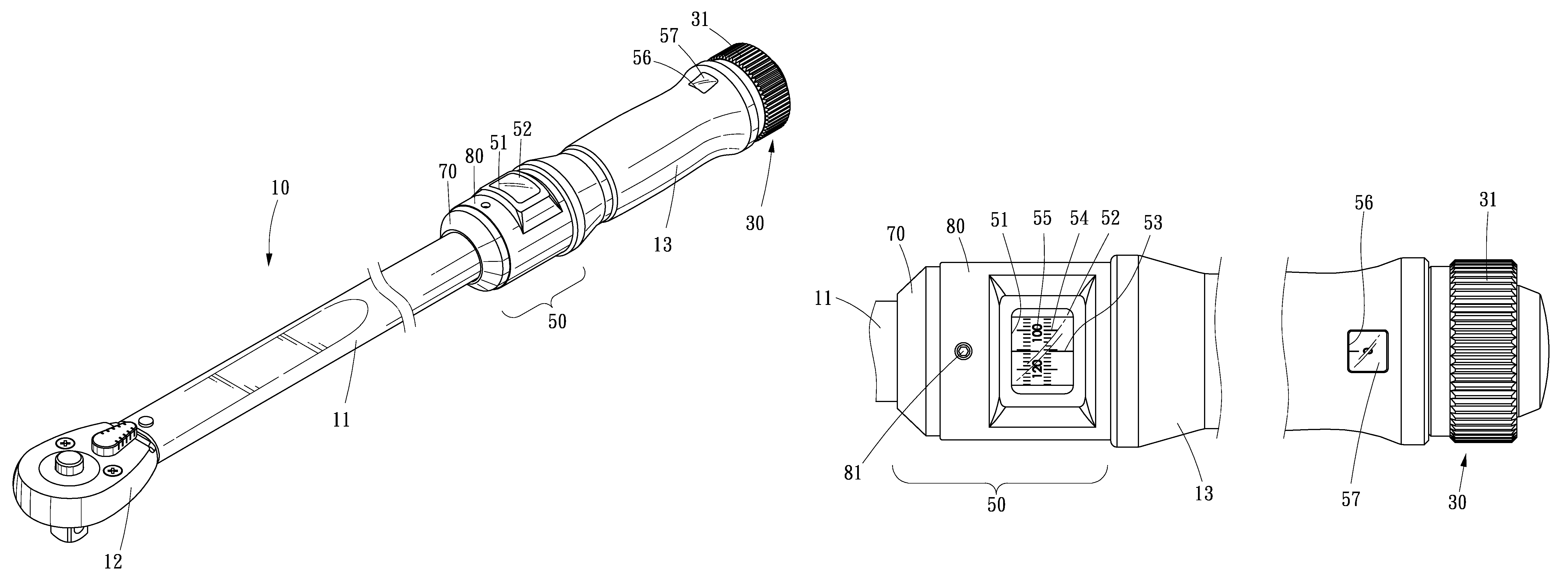
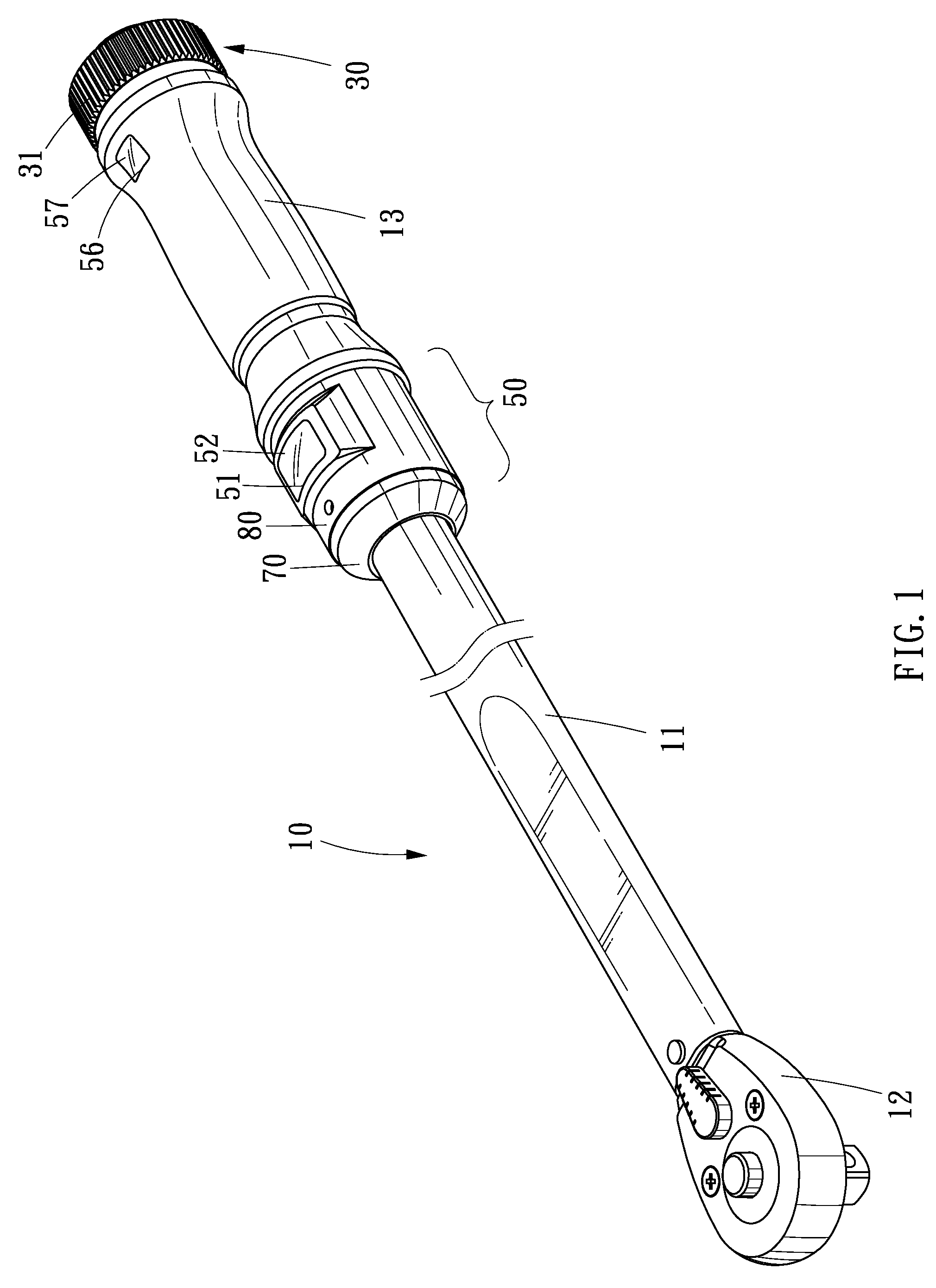
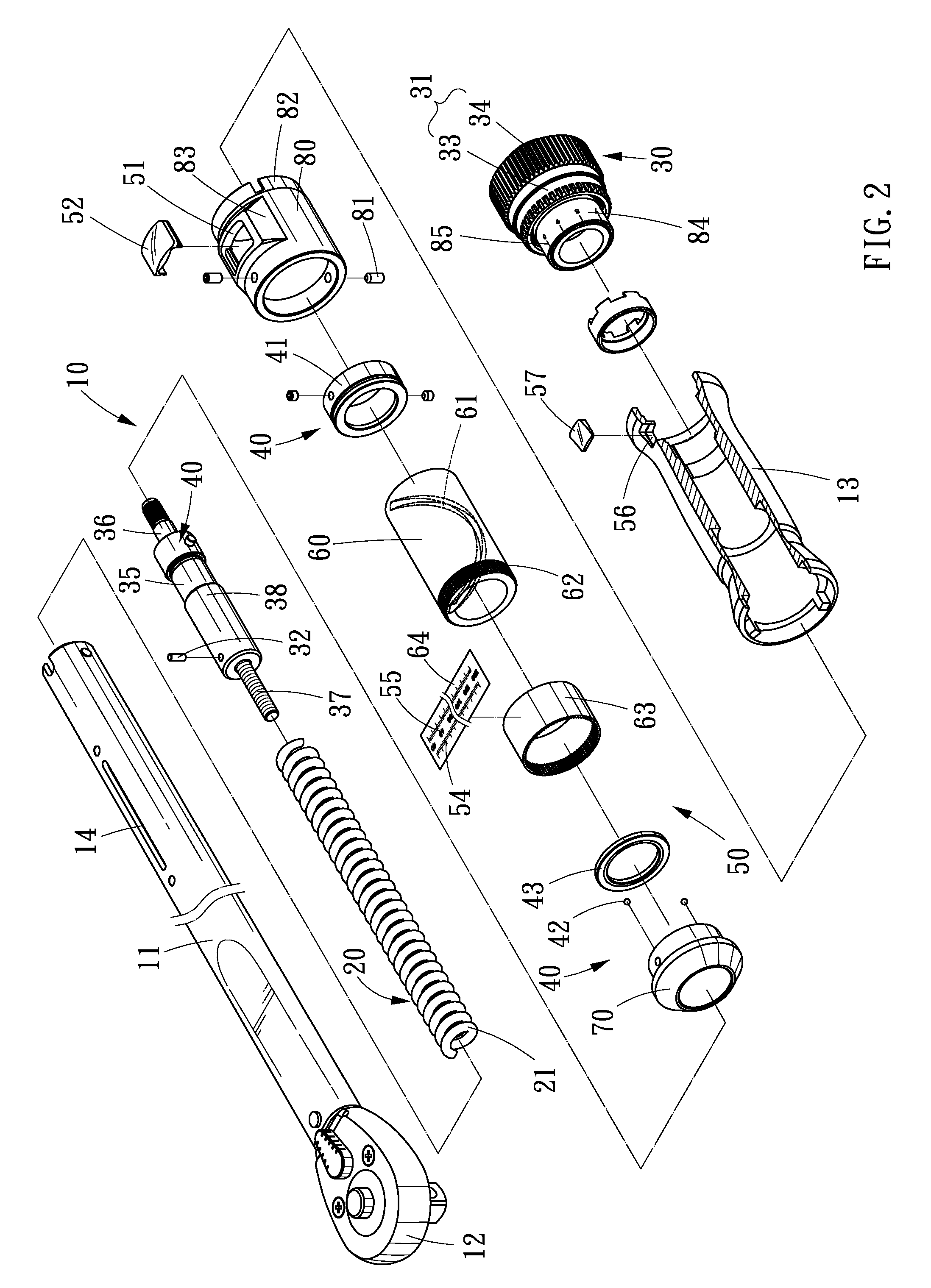
[0018]Referring to FIGS. 1 through 3, a wrench 10 includes a shank 11, a head 12, a handle 13, a torque assembly 20, a torque-setting device 30 and a torque-measuring device 50 according to the preferred embodiment of the present invention. The shank 11 is a tubular element with a slot 14 defined therein longitudinally. The handle 13 is attached to an end of the shank 11. The handle 13 includes a window 56 defined therein. A lens 57 is fit in the window 56. The lens 57 is preferably a magnifier.

[0019]The torque assembly 20 is located in the shank 11. The head 12 is attached to an opposite end of the shank 11 via the torque assembly 20. The torque assembly 20 includes a spring 21. Further details of the torque assembly 20 can be found in U.S. Pat. No. 4,870,879.

[0020]The torque-setting device 30 includes a knob assembly 31, a bolt 35, a pusher 38 and a pin 32. The pusher 38 is a tubular element with a thread extending on an internal side. The pusher 38 is located in the shank 11, aga...


PUM


Abstract

A wrench includes a shank including a slot defined therein longitudinally, a handle attached to an end of the shank, a head, a torque assembly for connecting the head to another end of the shank, a torque-setting device and a torque-measuring device. The torque-setting device includes a knob inserted in the handle and a pin movable in and along the slot as the knob is spun. The torque-measuring device includes a measurement sleeve and a collar. The measurement sleeve is rotationally located around the shank and includes a helical groove defined in an internal side and a scale provided on an external side. A portion of the pin is movably inserted in the helical groove so that the measurement sleeve is spun as the pin is moved in and along the slot. The collar is located around the shank and includes a window through which the scale is observable.

Description

BACKGROUND OF INVENTION[0001]1. Field of Invention[0002]The present invention relates to a wrench and, more particularly, to a wrench equipped with a precise torque-measuring device.[0003]2. Related Prior Art[0004]As disclosed in U.S. Pat. No. 4,870,879, a wrench includes a ratchet arm 1, a shank 3, a torque assembly 2 arranged between the ratchet arm 1 and the shank, a handle 40 connected to the shank, and a dial 41 connected to the torque assembly 2. The dial 41 is allowed to spin relative to the handle 40. The dial 41 includes a scale 411. The handle 40 includes a pointer 401. The dial 41 is spun to set a maximum value of torque that can be transmitted to the ratchet arm 1 from the shank 3 and the handle 40 via the torque assembly 2. The pointer 401 and the scale 411 are used to show the maximum value of torque. The scale is based on N-m, lb-ft or kg-m. The scale 411 however cannot show the maximum value of torque precisely.[0005]Such wrenches can be found in U.S. Pat. Nos. 2,205...

Claims


Application Information

Patent Timeline
Patent Type & Authority Patents(United States)
IPC IPC(8): B25B23/142
CPCB25B23/1427
Inventor WU, YI-MINWU, JIH-CHUN
Owner MATATAKITOYO TOOL
Learn More