Rotary-wing Mars UAV single-rotor system aerodynamic characteristics test device and torque test method and lift test method
A technology for aerodynamic characteristics and testing devices, which is used in measurement devices, aircraft component testing, and mechanical component testing. and other problems, to achieve the effect of high scope of application and flexibility, scientific and reasonable structural design
- Summary
- Abstract
- Description
- Claims
- Application Information
AI Technical Summary
Problems solved by technology
Method used
Image
Examples
specific Embodiment approach 1
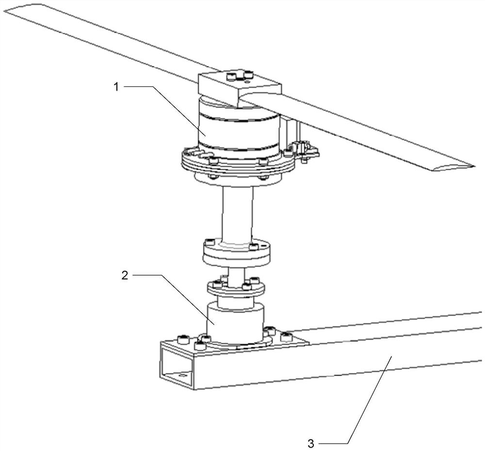
[0036] Specific implementation mode one: the following combination figure 1 and figure 2 Describe this embodiment, the aerodynamic characteristic testing device of the single-rotor system of the rotor-type Mars UAV described in this embodiment, it includes motion module 1, torque measurement module 2 and lift force measurement module 3;
[0037] The lower end surface of the motion module 1 is connected to the upper end of the torque measurement module 2, and the motion module 1 and the torque measurement module 2 are placed on the upper end surface of one end of the balance bar of the lift measurement module 3;
[0038] The motion module 1 is used to generate rotational motion, thereby generating torque and lift;
[0039] The torque measurement module 2 is used to measure the torque generated by the motion module 1;
[0040] The lift measuring module 3 is used to measure the lift generated by the motion module 1 .
specific Embodiment approach 2
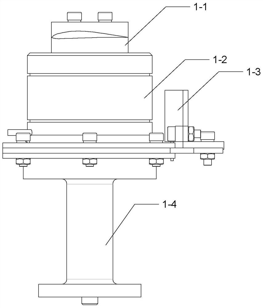
[0041] Specific implementation mode two: the following combination image 3 Describe this embodiment. This embodiment will further explain Embodiment 1. The motion module 1 includes a test rotor 1-1, an external high-speed brushless motor 1-2, a Hall element 1-3 and a No. 1 adapter rod 1-4. ;
[0042] The output shaft of the external high-speed brushless motor 1-2 drives the test rotor 1-1 to rotate. The shell of the external high-speed brushless motor 1-2 is connected to the upper end of the No. 1 adapter rod 1-4 through the bottom flange, and the Hall element 1-3 is connected to the bottom flange of the external high-speed brushless motor 1-2, the Hall element 1-3 is adjacent to and not in contact with the external high-speed brushless motor 1-2, and the Hall element 1-3 is used for external The speed of the high-speed brushless motor 1-2 is closed-loop controlled.
[0043] In this embodiment, the external high-speed brushless motor 1-2 is directly connected to the test ro...
specific Embodiment approach 3
[0044] Specific implementation mode three: the following combination Figure 4 and Figure 5 Describe this embodiment, this embodiment will further illustrate Embodiment 2, the torque measurement module 2 includes two sets of ball bearings 2-1, a laser transmitter 2-2, an upper grating ruler 2-3, a lower grating ruler 2-4, Laser receiver 2-5, No. 2 adapter rod 2-6, shell top cover 2-7, shell 2-8, lower grating seat 2-9 and shell bottom cover 2-10;
[0045]No. 2 transfer rod 2-6 is "T" shape, the upper end of No. 2 transfer rod 2-6 is connected with the lower end of No. 1 transfer rod 1-4, and the lower end of No. 2 transfer rod 2-6 is connected with the upper grating The ruler 2-3 is connected, the shell top cover 2-7, the shell 2-8 and the shell bottom cover 2-10 are connected in turn by screws, the lower grating ruler 2-4, the lower grating seat 2-9 and the shell bottom cover 2-10 in turn connected, and the lower grating seat 2-9 is located at the center of the shell botto...
PUM
 Abstract
Description
Claims
Application Information
 - R&D
- Intellectual Property
- Life Sciences
- Materials
- Tech Scout
- Unparalleled Data Quality
- Higher Quality Content
- 60% Fewer Hallucinations
Browse by: Latest US Patents, China's latest patents, Technical Efficacy Thesaurus, Application Domain, Technology Topic, Popular Technical Reports.
© 2025 PatSnap. All rights reserved.Legal|Privacy policy|Modern Slavery Act Transparency Statement|Sitemap|About US| Contact US: help@patsnap.com


