
Secure strap systems

a technology of secure straps and straps, applied in the direction of hose connections, snap fasteners, buckles, etc., can solve the problems of cutting into the bound items, lack of selective fastening and/or release, undesirable limitations of the prior art, etc., and achieve the effect of efficient and effective us

Active Publication Date: 2013-02-12
MINISTRAP LLC
View PDF57 Cites 13 Cited by
  • Summary
  • Abstract
  • Description
  • Claims
  • Application Information

AI Technical Summary

Benefits of technology

The present invention provides a fastening strap system that can be used efficiently and effectively as an adjustable belt or strap without significant material design changes or functional limitations. It allows for the selective and independent binding and release of multiple bundles of items from one another. It is less likely to unintentionally come undone. It can be easily anchored and tailored by a user to fit different applications. It is efficient and inexpensively manufactured and efficient to use.

Problems solved by technology

While generic tying or binding materials exist, such as string, tape, etc., these materials have many drawbacks related to tape glue residue, the thin material of the material causing cuts into the bound items, and a lack of selective fastening and / or release.
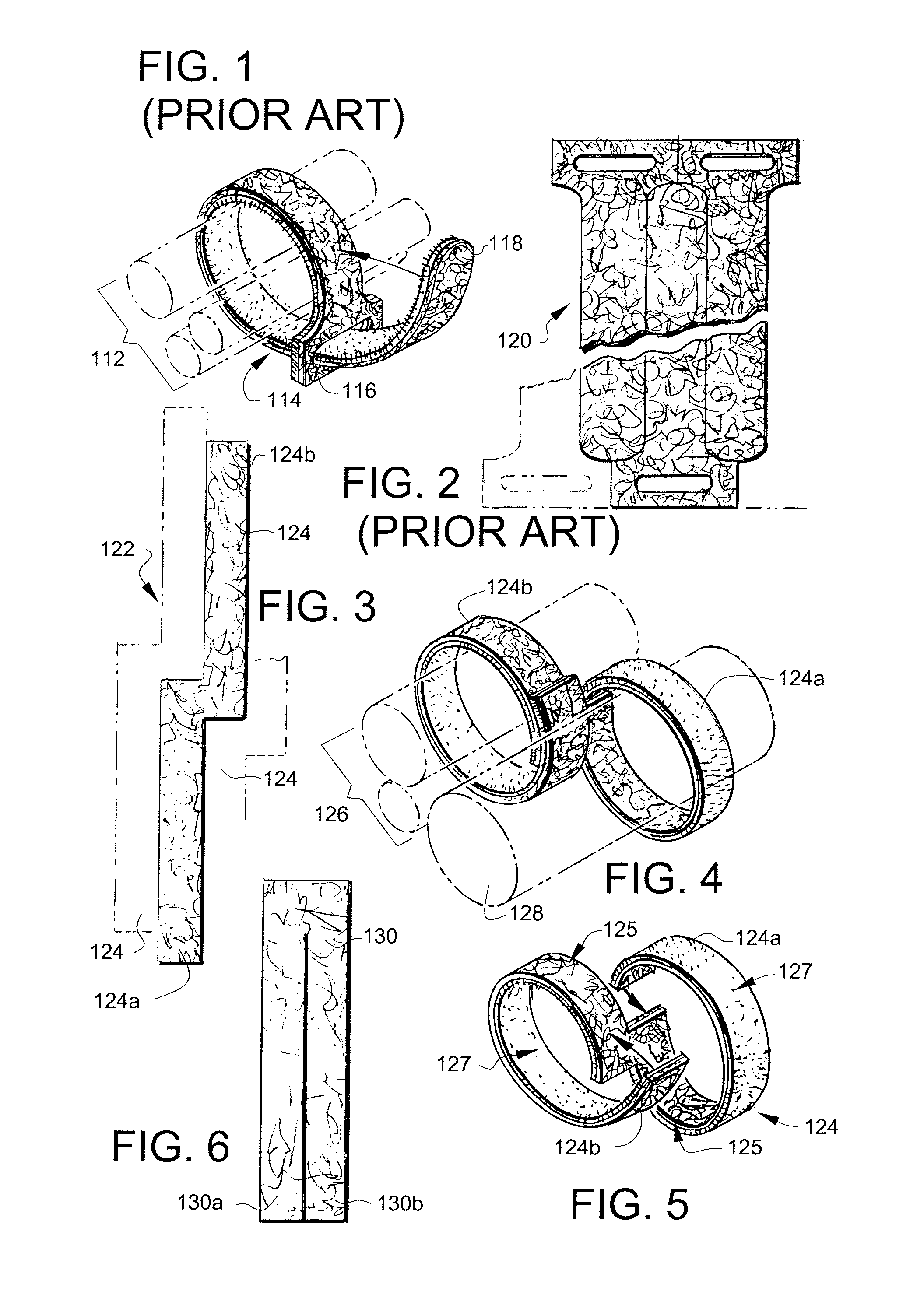
Although some fastening systems exist that utilize hook and loop material, some problems remain. FIG. 1 and FIG. 2 show a prior art fastening strap.
There are however, undesirable limitations to this prior art.
For example, the pulling end 118 of the GET A GRIP® strap has the disadvantage of being extremely short, and thus it is practically incapable of bundling another object to a first object.

Method used


Image

  • Secure strap systems
  • Secure strap systems
  • Secure strap systems

Examples


Embodiment Construction

[0075]Preferred embodiments and best mode of the present invention are described below. In such discussion, reference will be made to hook and loop fasteners. It is noted that the present invention, in a described embodiment, provides a simple dispensing mechanism for dispensing straps of variable length determined by the end user, having been preferably provided the material, preferably pre-cut by a manufacturer (to provide such advantages).

[0076]FIG. 20 shows a close-up edge view of a hook and loop material 160 as used in embodiments of the present invention. Preferably, the hook and loop material 160 comprises loop material 162 and hook material 164. Preferably, hook and loop material may also be made, according to the present invention, as illustrated in FIG. 22.

[0077]FIG. 22 shows a plan view, showing both front and rear surfaces, of an alternating hook / loop material used in some embodiments of the present invention. Preferably, the hook and loop material 170 comprises, on a fi...


PUM


Abstract

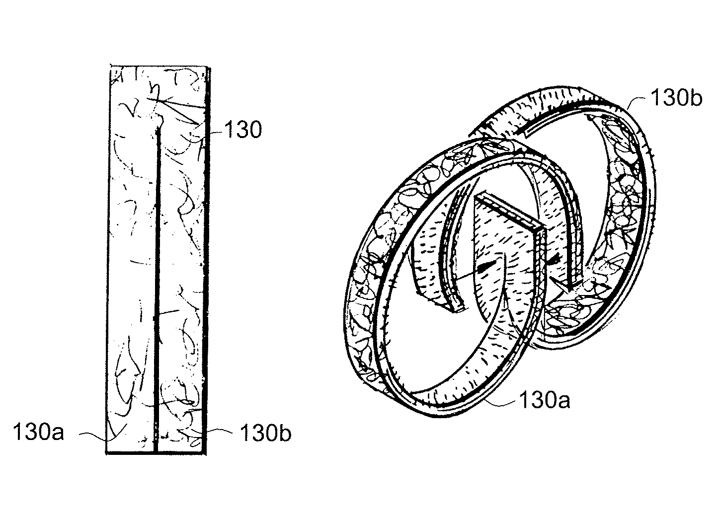
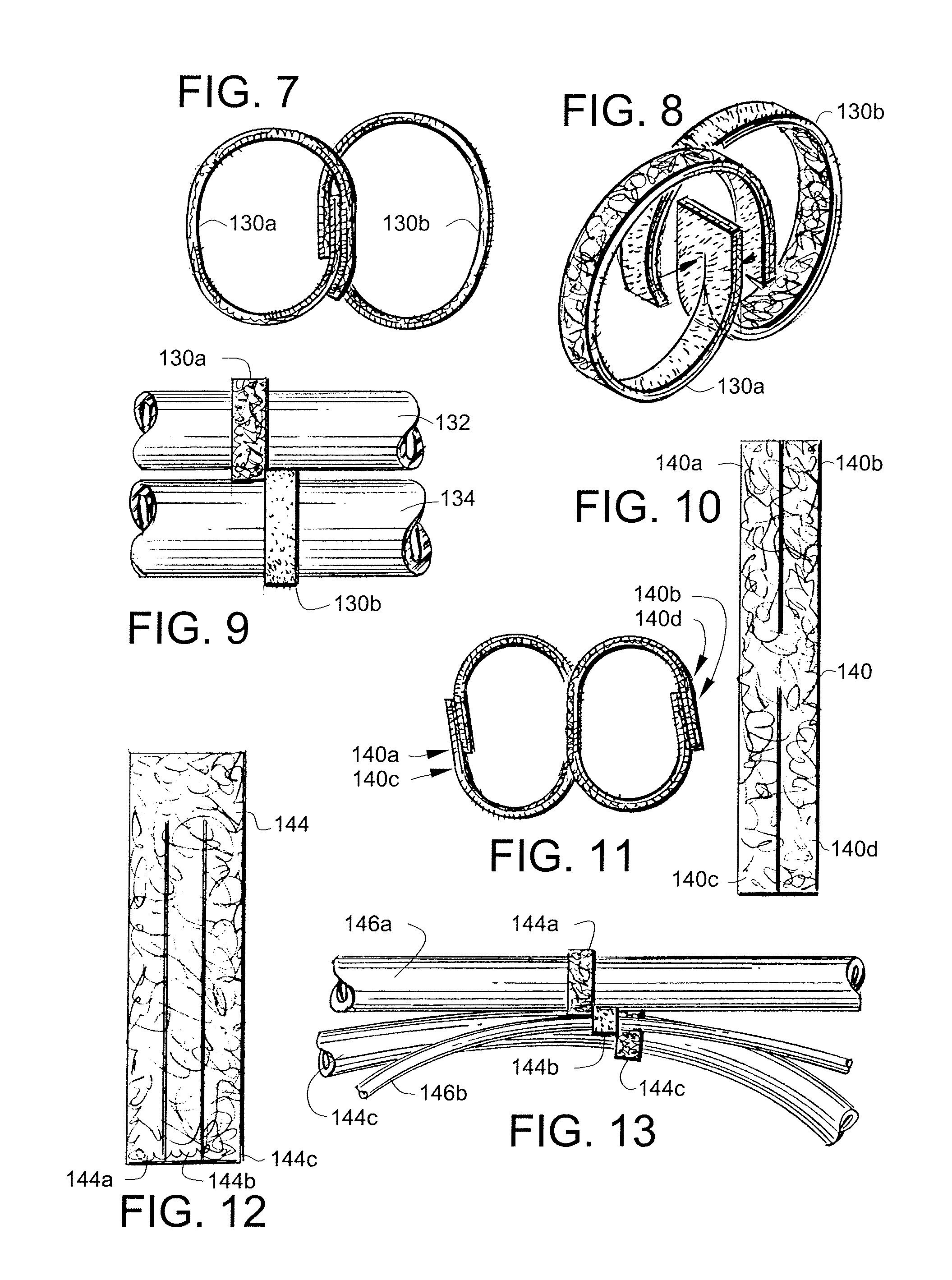
A strap system for selectively and independently binding and / or releasing at least one sets of essentially longitudinal objects, such as wires, from one another. A continuous strip of such two-sided material may be stored on a reel and is designed so that a user may select a preferred length and configuration for a particular use by making a single cut of the material strip from the reel-strip end.

Description

CROSS-REFERENCE TO RELATED APPLICATIONS[0001]The present application is a continuation-in-part of related patent application Ser. No. 11 / 670,829, filed Feb. 2, 2007, entitled “SECURE STRAP SYSTEMS”, which is a continuation-in-part of related patent application Ser. No. 10 / 465,162, filed Jun. 18, 2003, entitled “LOOPABLE, SECURE MULTIPLE-FASTENING-STRAP SYSTEMS”, which is a continuation-in-part of related application Ser. No. 10 / 094,524, filed Mar. 7, 2002, entitled “FASTENING STRAP SYSTEM”, which is related to and claims priority from prior provisional patent application Ser. No. 60 / 274,033, filed Mar. 7, 2001, entitled “FASTENING STRAP SYSTEM”, the contents all of which are incorporated herein by this reference and are not admitted to be prior art with respect to the present invention by mention is this cross-reference section.BACKGROUND[0002]This invention relates to fastening strap systems. More particularly, it relates to such strap systems, using fastenable and releasable mater...

Claims


Application Information

Patent Timeline
IPC IPC(8): A44B18/00B65D63/10
CPCB65D63/10B65D2313/02Y10T24/27Y10T24/14Y10T24/2708
Inventor SCHULTZ, JOSEPH P.
Owner MINISTRAP LLC
Learn More