
Debugging device and debugging method

a debugging device and a technology of a debugging device, applied in the field of debugging devices and debugging methods, can solve the problems of conventional debugging devices not being able to distinguish between information of a code, the debugging operator can easily find the problematic code, and neither can the conventional debugging devi

Active Publication Date: 2013-02-05
KK TOSHIBA
View PDF29 Cites 16 Cited by
  • Summary
  • Abstract
  • Description
  • Claims
  • Application Information

AI Technical Summary

Benefits of technology

The present invention provides a debugging device that can analyze information about a code that does not need to be debugged and output it for further analysis. The device can also selectively display or hide the code based on its analysis. This helps to efficiently use the debugging device and prevent unnecessary interruptions while analyzing the code. The technical effect of this invention is improved debugging efficiency and efficiency in code analysis.

Problems solved by technology

Accordingly, the debugging operator can easily find the problematic code.
However, while conventional debugging devices can display an auxiliary message in the problematic code as described above, the conventional debugging devices cannot distinguish between information of a code that does not need to be debugged which is generated by optimization of the compiler during debugging and information of a code that needs to be debugged.
In addition, the conventional debugging devices can neither add a massage to a start position and an end position of the distinguished code that does not need to be debugged, nor hide the code itself.

Method used


Image

  • Debugging device and debugging method
  • Debugging device and debugging method
  • Debugging device and debugging method

Examples


Embodiment Construction

[0026]Hereinafter, an embodiment of the present invention will be described in detail with reference to the drawings.

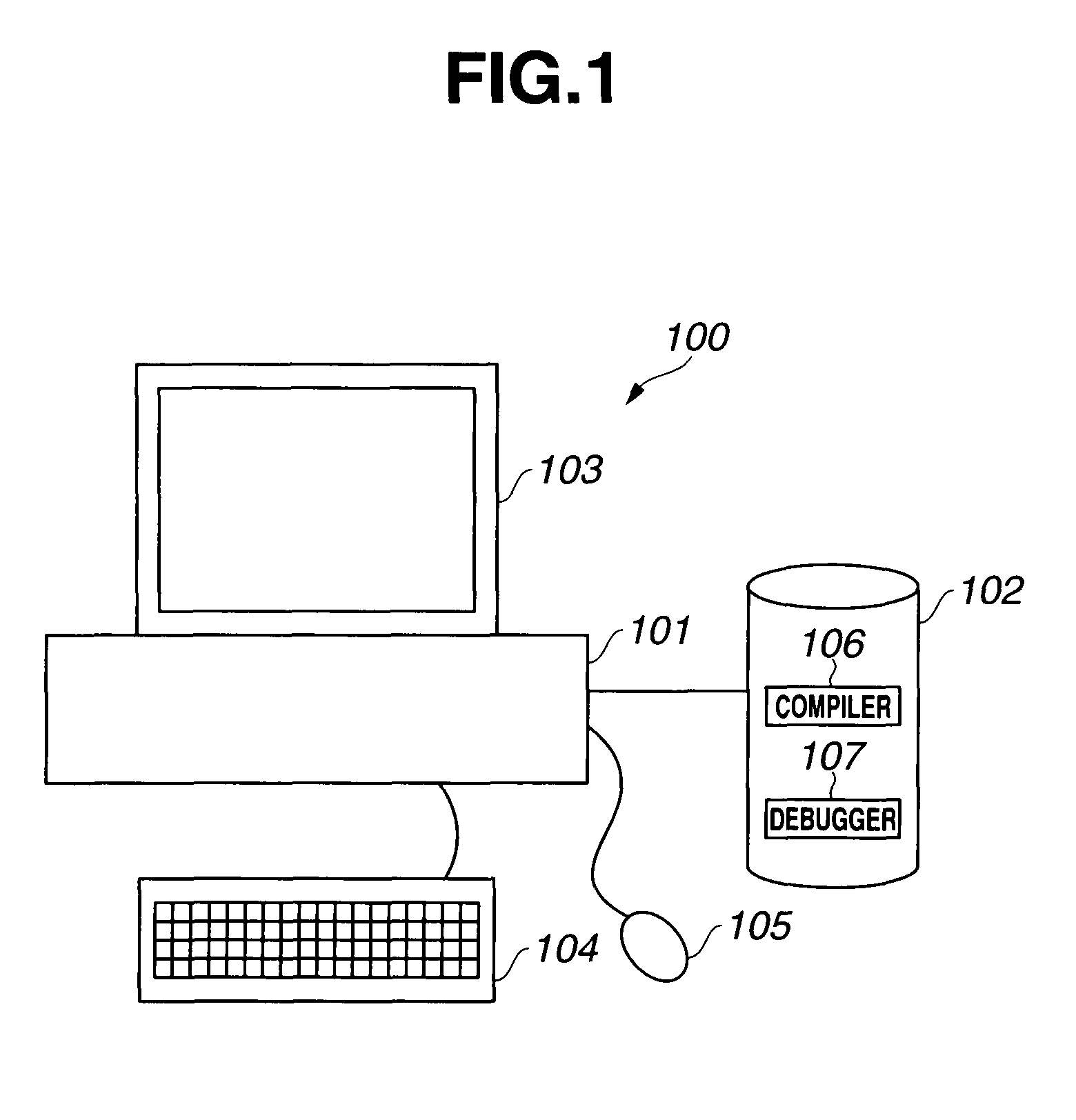
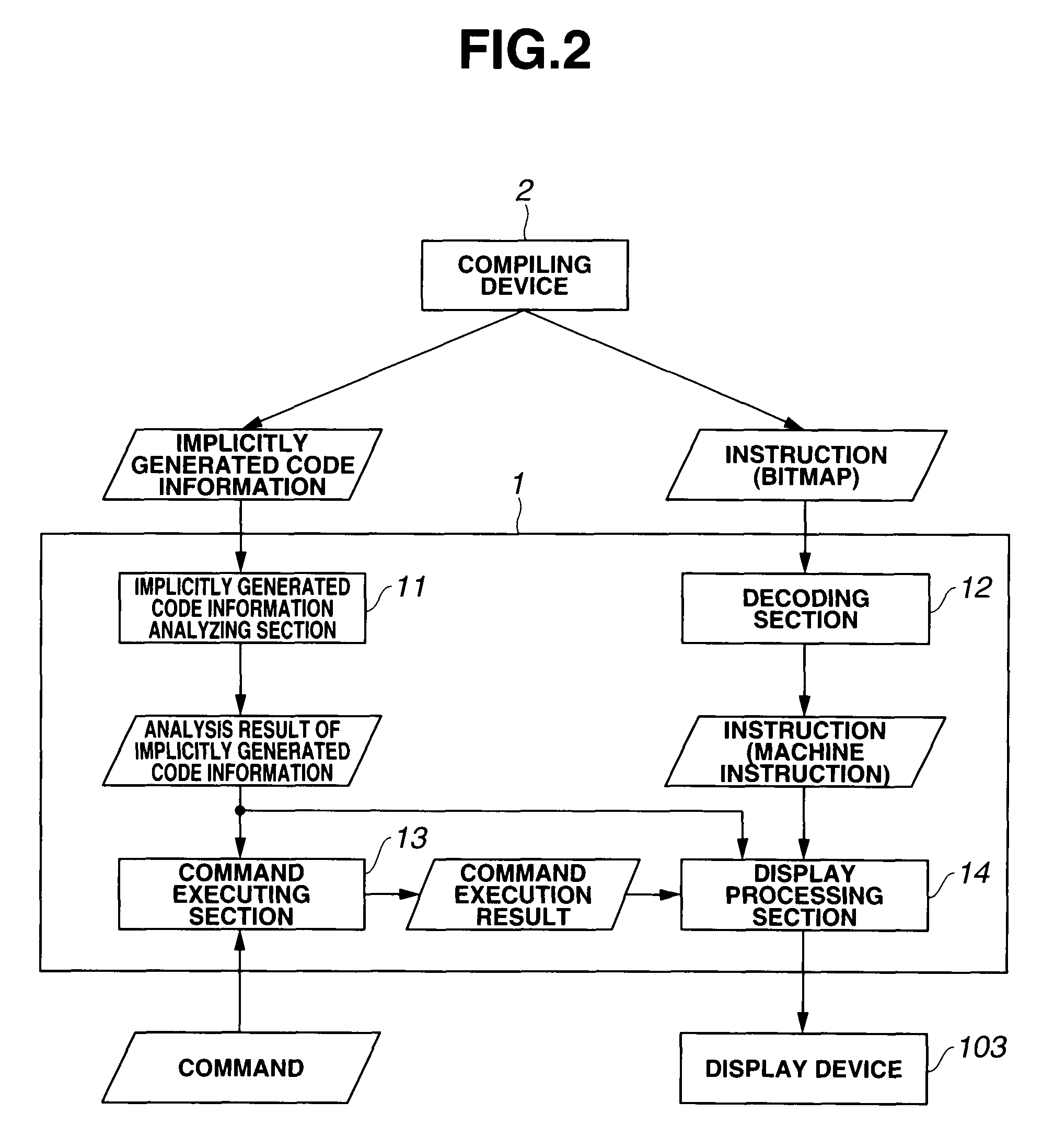
[0027]First, a debugging device according to an embodiment of the present invention will be described based on FIGS. 1 and 2. FIG. 1 is a diagram of a configuration of a program generating device including a debugging device according to the present embodiment.

[0028]A program generating device 100 is configured to include a main body device 101 having a central processing unit (CPU), a main memory, and the like, a storage device 102 storing various data, and a display device 103 displaying various data.

[0029]The main body device 101 is a main body of a computer device such as a personal computer, and is connected with a keyboard 104 and a mouse 105 as input devices. The main body device 101 executes various programs based on instructions from the input devices.

[0030]In the storage device 102, a compiler 106 having a program of a compiling function and a debugger 107 h...


PUM


Abstract

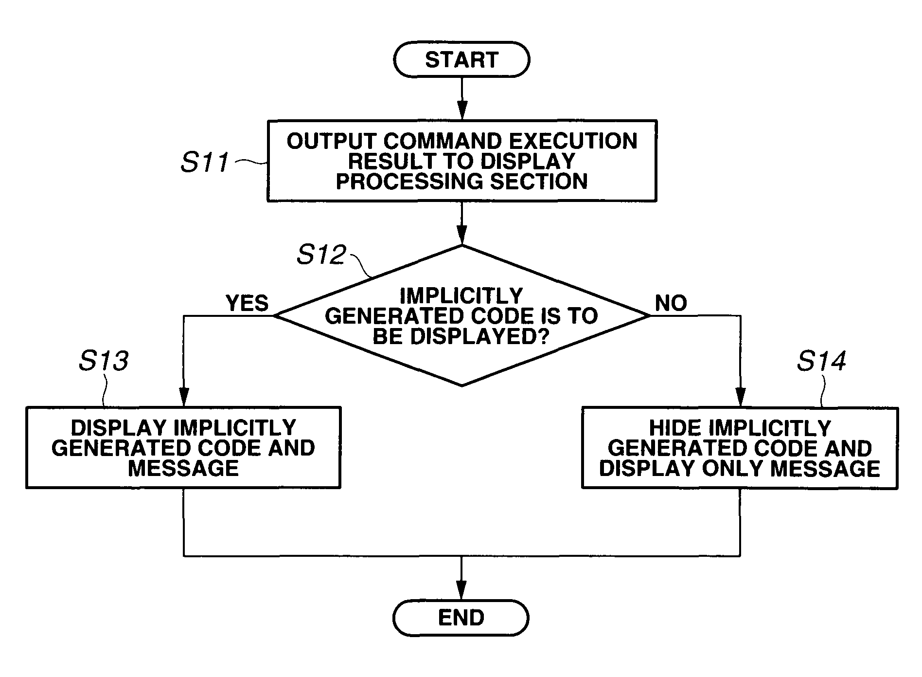
A debugging device configured to debug a program includes an analysis section configured to analyze information of a code that does not need to be debugged in which a predetermined processing instruction is described, the code being generated by optimization of a compiler for a source code of the program, and an output section configured to output processing content information, a start address, and an end address of the code that does not need to be debugged which are obtained by the analysis.

Description

CROSS REFERENCE TO RELATED APPLICATION[0001]This application is based upon and claims the benefit of priority from the prior Japanese Patent Application No. 2007-309260 filed on Nov. 29, 2007; the entire contents of which are incorporated herein by this reference.BACKGROUND OF THE INVENTION[0002]1. Field of the Invention[0003]The present invention relates to a debugging device and a debugging method, and particularly to a debugging device and a debugging method which debug a program.[0004]2. Description of the Related Art[0005]Conventionally, in creating a program, debugging is performed using a debugging device in order to check whether or not the program operates correctly. The debugging device receives as input an object program generated by a compiling device, and displays a corresponding source code or assembly code on a graphical user interface (hereinafter referred to as GUI).[0006]The debugging device has functions of performing break point setting, step execution, and the l...

Claims


Application Information

Patent Timeline
Patent Type & Authority Patents(United States)
IPC IPC(8): G06F9/44G06F11/00
CPCG06F11/3628G06F11/3644
Inventor ODA, YUICHI
Owner KK TOSHIBA
Learn More