
Regulator unit and method for regulating a flap opening of a flap situated in a mass flow line

a technology of mass flow and control unit, which is applied in the direction of water feed control, lighting and heating apparatus, machines/engines, etc., to achieve the effect of stable regulating performance, rapid and easy numerically, and stable transient respons

Active Publication Date: 2013-02-05
ROBERT BOSCH GMBH
View PDF21 Cites 5 Cited by
  • Summary
  • Abstract
  • Description
  • Claims
  • Application Information

AI Technical Summary

Benefits of technology

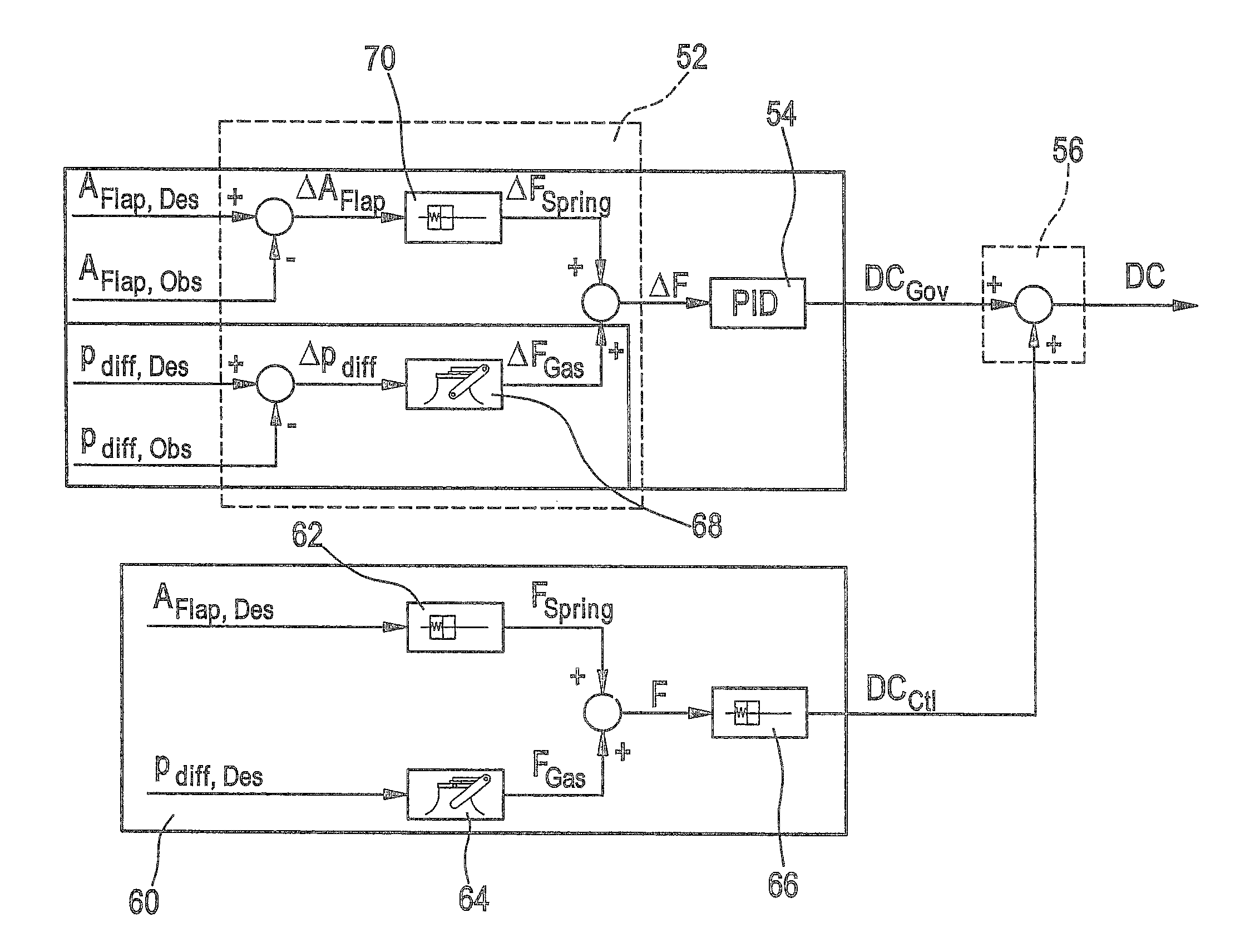
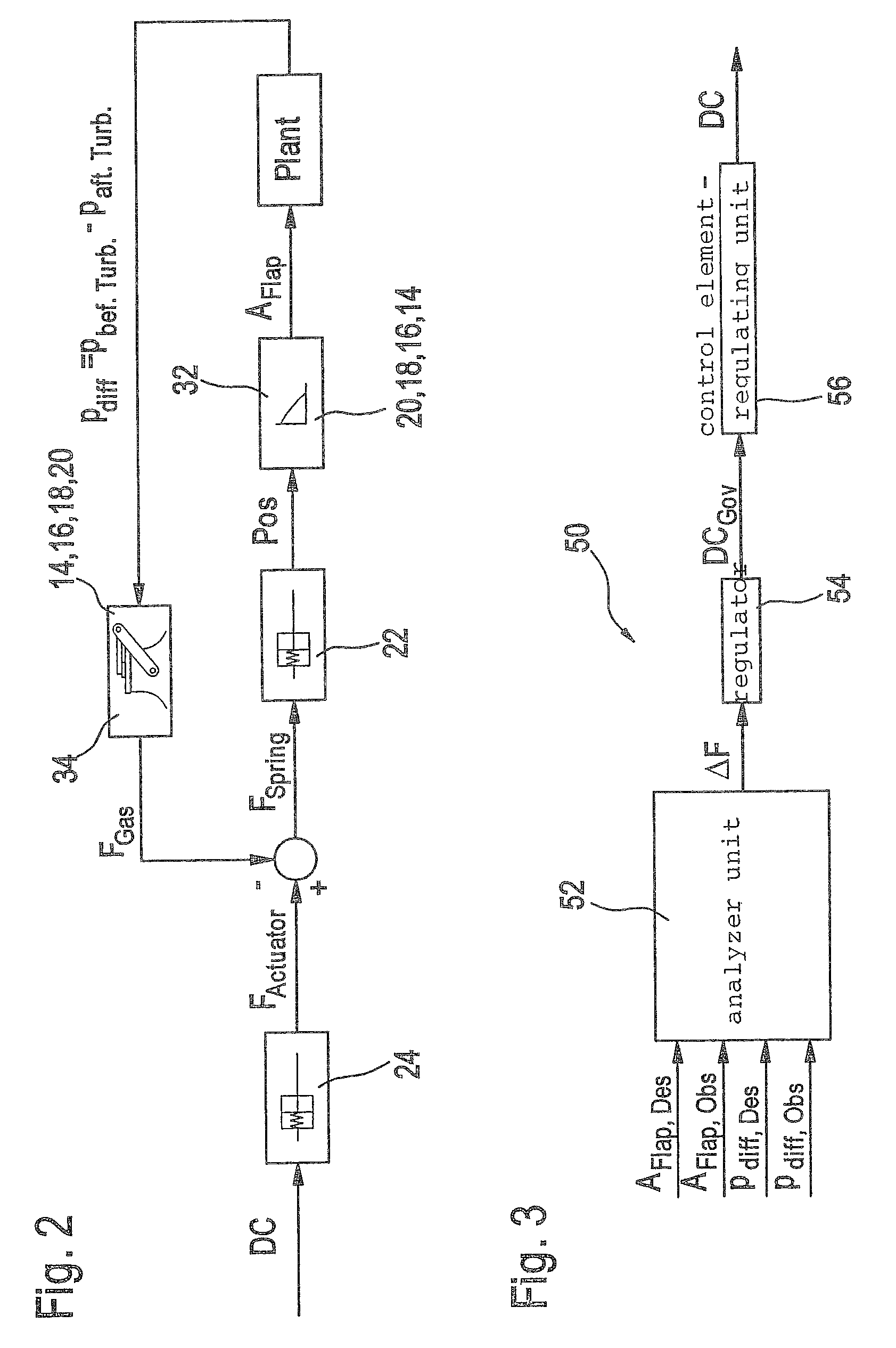
[0012]The analyzer unit may also be designed to provide a differential pressure signal based on the difference between a desired pressure difference and differences upstream and downstream from the flap, to ascertain a differential pressure force signal on the basis of the differential pressure signal using a regulating pressure characteristic curve and to provide the analysis signal on the basis of the differential pressure force signal. This offers the advantage that analysis of the pressure differences in the analyzer unit may be performed very rapidly and easily numerically (e.g., by lookup in a lookup table), which also has advantageous effects on the regulating speed and thus a rapid transient response.
[0013]Additionally or alternatively, the analyzer unit may also be designed to form a flap difference signal from the relationship between the desired flap opening and an observed flap opening to determine from the flap difference signal a differential area force signal using a predetermined regulating area characteristic curve and to provide the analysis signal on the basis of the differential area force signal. This offers the advantage that analysis of the flap opening in the analyzer unit may be performed very rapidly and easily numerically (e.g., by lookup in a lookup table), which in turn has an advantageous effect on the regulating speed and thus a rapid transient response.
[0014]It is also favorable if the precontrol unit is designed to ascertain the precontrol signal from the predefined desired difference between the pressures upstream and downstream from the flap on the basis of a predefined precontrol pressure characteristic curve. In this case specifically the analyzer unit may be designed to perform the analysis signal using a regulating pressure characteristic curve based on the precontrol pressure characteristic curve. This offers the advantage that only a corresponding precontrol pressure characteristic curve may be input in the regulator unit, this precontrol pressure characteristic curve being usable for the precontrol unit on the one hand and also for the analyzer unit on the other hand. This results in a simple method of providing this characteristic curve before storing the characteristic curve in the regulator unit on the one hand and also results in a stable regulating performance on the other hand because regulation is performed on the basis of the connected regulation characteristic curves.
[0015]The regulating pressure characteristic curve may also be representable as a derivative of the precontrol pressure characteristic curve. This is a simple implementation of the regulating pressure characteristic curve, which is derivable numerically from the precontrol pressure characteristic curve in an uncomplicated manner. In particular, proven and easy to implement methods are available for efficiently forming a derivative, so that only the precontrol pressure characteristic curve for the precontrol unit need be saved.
[0016]Accordingly the precontrol unit may also be designed similarly to ascertain the precontrol signal of the predefined desired flap opening on the basis of a predefined precontrol area characteristic curve such that the analyzer unit may then be designed to perform the analysis signal using a regulation area characteristic curve based on the precontrol area characteristic curve. In this regard, it may also be pointed out that only the precontrol area characteristic curve need be stored in the precontrol unit from which the regulation area characteristic curve may then be determined in a numerically efficient manner.
[0017]Similarly, the regulation area characteristic curve may also be represented as a derivative of the precontrol area characteristic curve. This is a numerically simple implementation of the method of providing the regulation area characteristic curve, so that only the precontrol area characteristic curve need be stored in the precontrol unit.

Problems solved by technology

In most cases, however, due to interference variables in the real surroundings, an additional regulator is needed to compensate for deviations that occur.

Method used


Image

  • Regulator unit and method for regulating a flap opening of a flap situated in a mass flow line
  • Regulator unit and method for regulating a flap opening of a flap situated in a mass flow line
  • Regulator unit and method for regulating a flap opening of a flap situated in a mass flow line

Examples


Embodiment Construction

[0026]In the following Figures, the same or similar components may be provided with the same or similar reference numerals. In addition, any dimensions and measurements that are given are only examples, so the present invention is not limited to these dimensions and measurements. Furthermore, the figures and the drawings, their description and the claims include numerous features in combination. It is clear to those skilled in the art that these features may also be considered individually or may be combined into other combinations not explicitly described here.

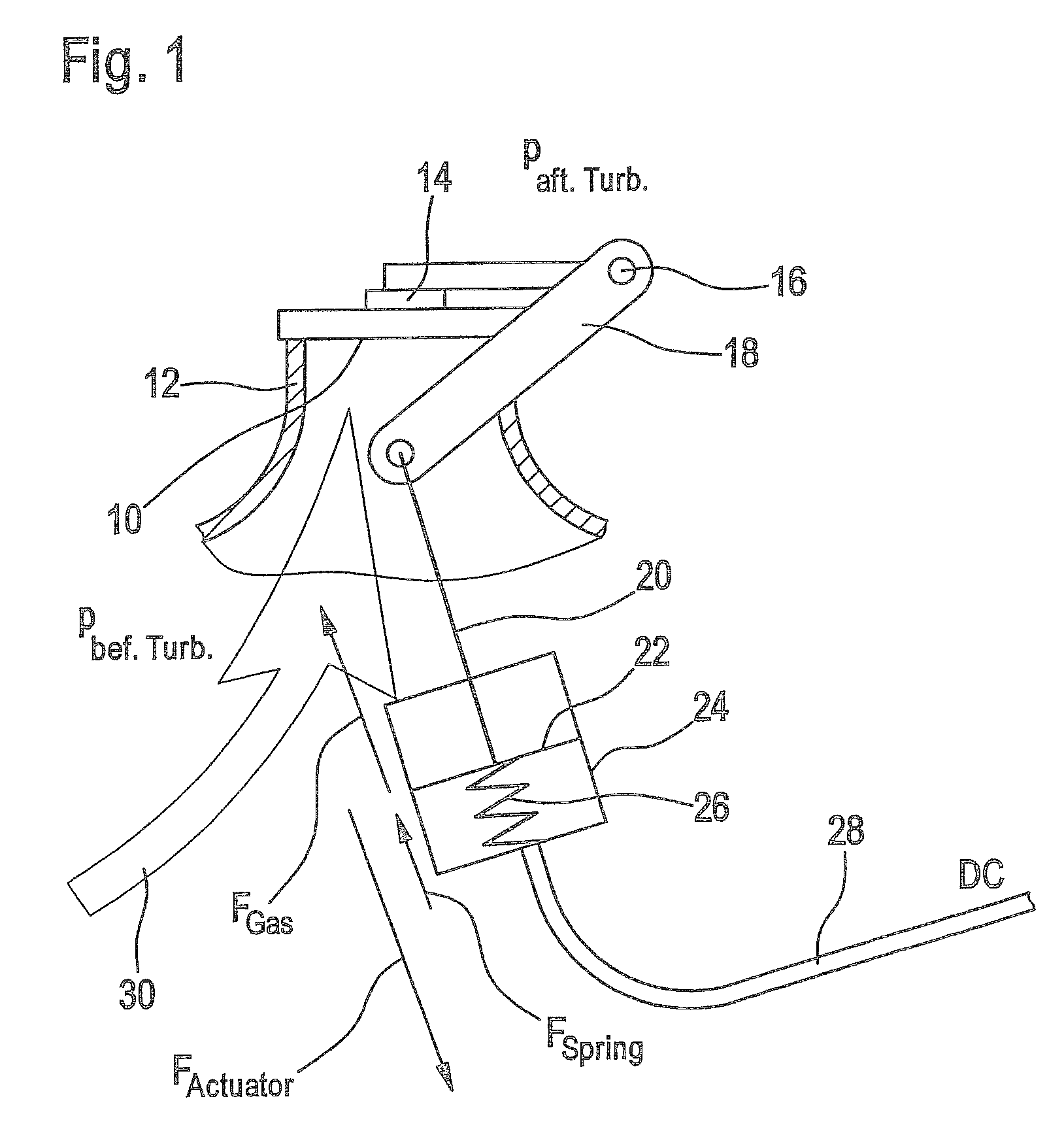
[0027]The environment where example embodiments of the present invention is used is explained first in greater detail below on the basis of FIGS. 1 and 2. Example embodiments of the present invention may be provided to close an opening 10 in a fluid line 12 using a flap 14, as illustrated in FIG. 1. Fluid line 12 may be an intake connection for a turbocharger or a line connected in parallel with a turbocharger. Fluid line 12,...


PUM


Abstract

A regulator unit for regulating a flap opening of a flap arranged in a mass flow line includes: an analyzer unit which is designed for providing an analysis signal on the basis of a predefined desired pressure difference and a difference between pressures upstream and downstream from the flap; a regulator which is designed for determining a trigger signal from the analysis signal according to a regulating characteristic; and a control element-regulating unit which is designed for regulating the flap opening of the flap in the mass flow line in response to the trigger signal.

Description

CROSS-REFERENCE TO RELATED APPLICATIONS[0001]The present application claims priority to Application No. 10 2008 005 648.0, filed in the Federal Republic of Germany on Jan. 23, 2008, which is expressly incorporated herein in its entirety by reference thereto.FIELD OF THE INVENTION[0002]The present invention relates to a regulator unit for regulating a flap opening of a flap situated in a mass flow line and to a method for regulating a flap opening of a flap situated in a mass flow line.BACKGROUND INFORMATION[0003]Flaps are often provided in the inlet and outlet air lines for the internal combustion engine for controlling an internal combustion engine. These flaps may be opened or closed to permit regulation of a mass flow of a fluid (e.g., air, a fuel-air mixture, exhaust gas or a liquid fuel). The flap (in the form of a throttle member) which is often attached on one side is moved slightly to open a variable line cross section of the line for the flow of the fluid.[0004]If a device ...

Claims


Application Information

Patent Timeline
Patent Type & Authority Patents(United States)
IPC IPC(8): F16K31/12
CPCF02D9/1065F02D9/04F02D2009/0264F02D2009/0266Y10T137/7329Y10T137/7352Y10T137/776Y10T137/7898
Inventor BLEILE, THOMASWITTMER, ANDRE
Owner ROBERT BOSCH GMBH
Learn More