
System and apparatus for sequential processing of analytes

Inactive Publication Date: 2013-01-29
ILLUMINA INC
View PDF187 Cites 93 Cited by
  • Summary
  • Abstract
  • Description
  • Claims
  • Application Information

AI Technical Summary

Benefits of technology

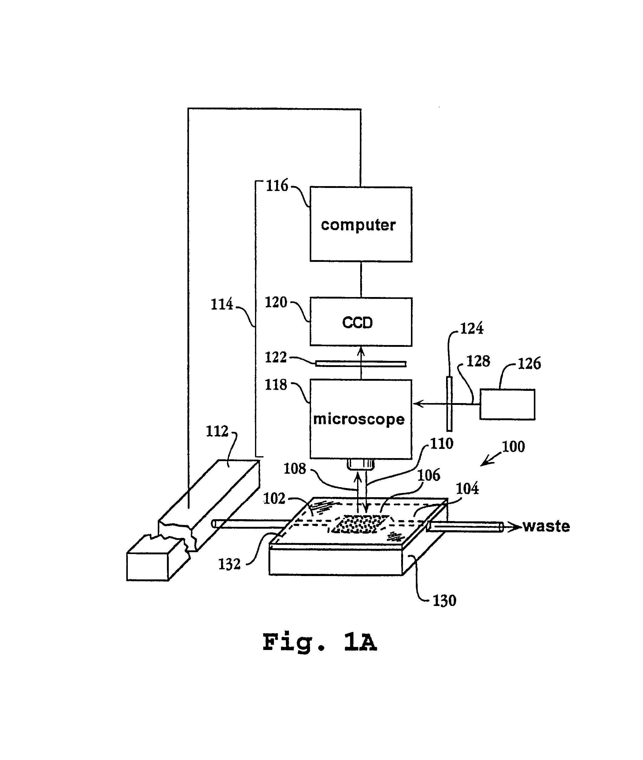
This patent is about a system and process for analyzing microparticles that carry analytes. The system includes a flow chamber where the microparticles are placed in a planar array and a reagent delivery system to add processing reagents sequentially to the microparticles. Optical signals generated by the interactions between the processing reagents and the analytes on the microparticles are detected and recorded using a detection system. The patent also includes a system for simultaneously monitoring the interactions of multiple reagents with multiple analytes on microparticles using a planar array. The technology also allows for the simultaneous analysis of the nucleotide sequences of polynucleotides anchored to microparticles.

Problems solved by technology

However, handling and manipulating large numbers of microparticles, e.g. tens to hundreds of thousands, for carrying out specific chemical and / or biochemical analyses gives rise to many difficulties, including whether sufficient signal is generated on individual microparticles for detection, how to track individual microparticles through multiple steps of a process, mechanical strength of microparticles under pressure or flow conditions, the ability to uniformly deliver reagents to microparticles for carrying out steps of an analytical process, whether clumping or other inappropriate interaction of microparticles and / or reagents occurs, whether or adsorption of analytes and / or processing reagents onto vessel walls occurs, whether protein reagents or analytes denature causing a disruption of reagent distribution and access, whether adjacent microparticles will interact, e.g. to degrade or obscure a signal or to inhibit reagent access, and the like.

Method used


Image

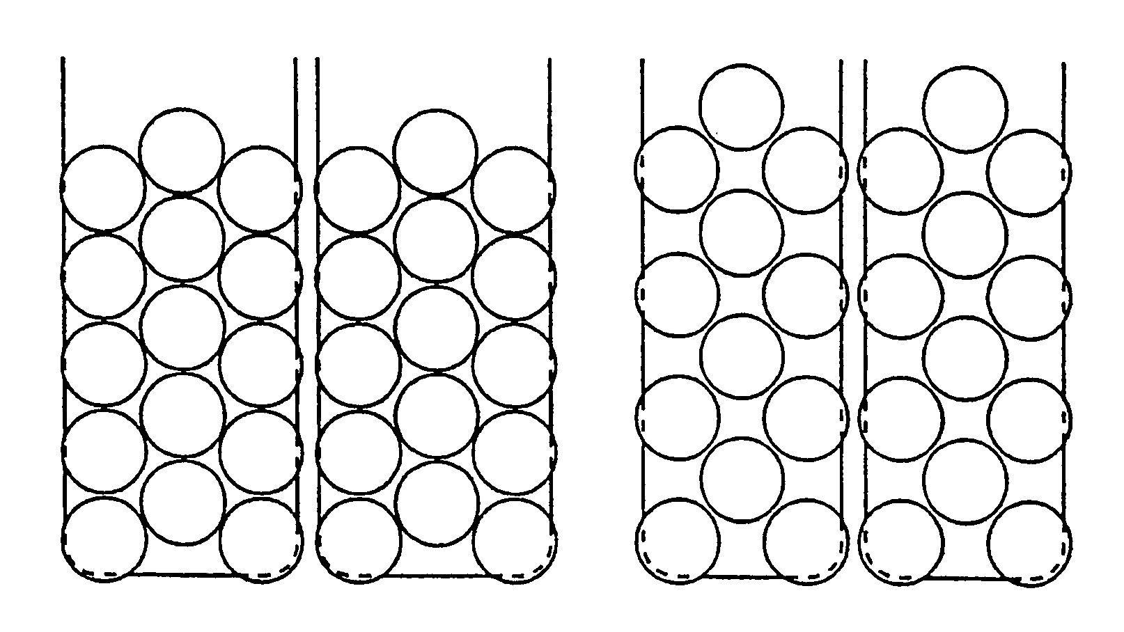
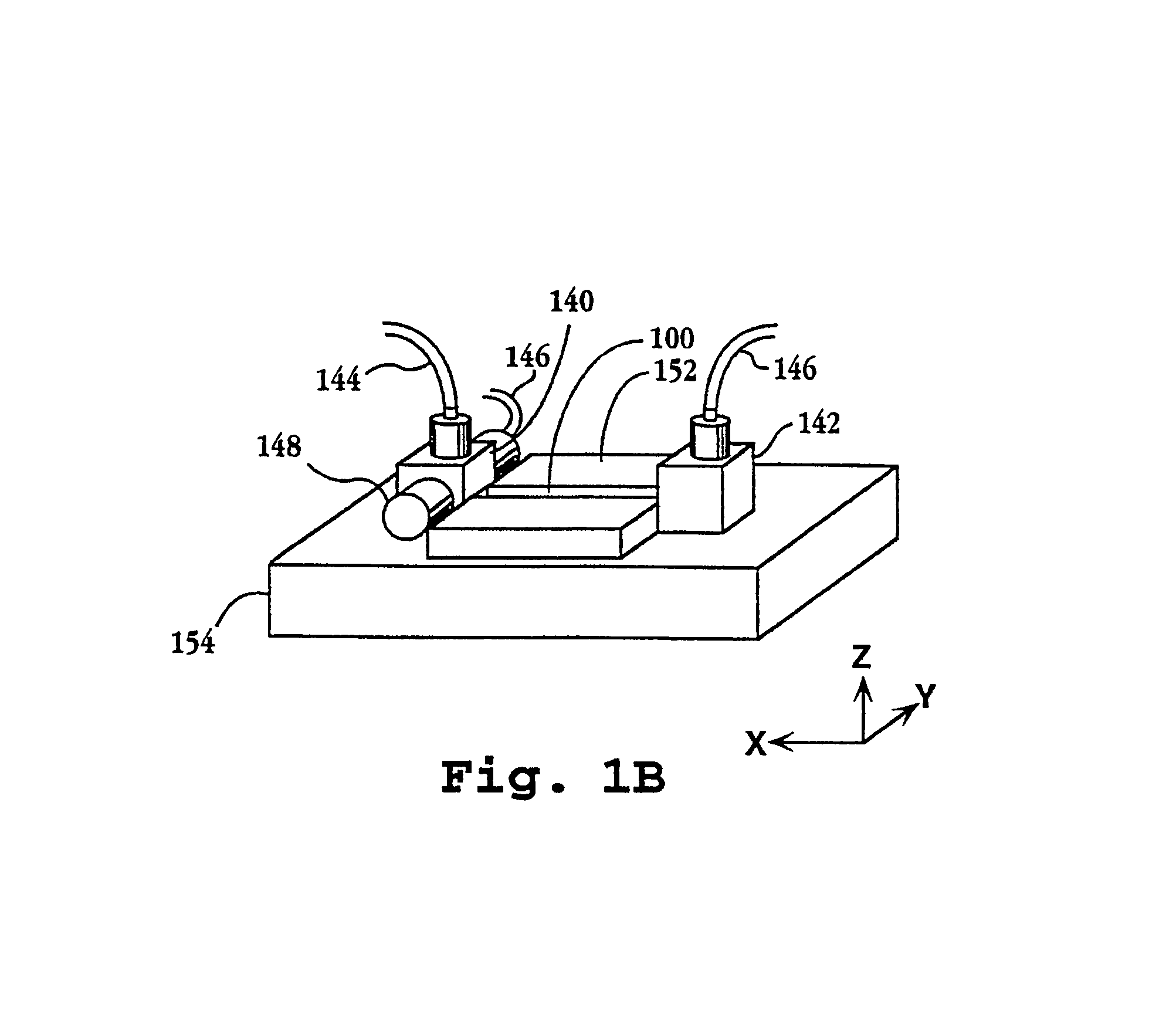
  • System and apparatus for sequential processing of analytes
  • System and apparatus for sequential processing of analytes
  • System and apparatus for sequential processing of analytes

Examples


Embodiment Construction

[0027]The system and apparatus of the invention is particularly applicable to the analysis of molecules that can be anchored in populations of duplicate copies to particulate solid phase supports. That is, in accordance with the invention, each analyte of a population is present on at least one microparticle in a quantity sufficient for the type of analysis being performed. For example, if combinatorially synthesized peptides on the microparticles are screened against a soluble receptor protein for detecting those that form stable complexes, the number of peptides available for binding on the surface of the microparticles must be large enough to generate a detectable signal when a binding event occurs. Of course, many additional factors well known in the art will present additional design constraints, such as the nature of the system for generating optical signals, the concentration of receptors, pH, salt concentration, the density and accessibility of the peptides on the microparti...


PUM

PropertyMeasurementUnit
diametersaaaaaaaaaa
diametersaaaaaaaaaa
pHaaaaaaaaaa

Abstract

An apparatus and system are provided for simultaneously analyzing a plurality of analytes anchored to microparticles. Microparticles each having a uniform population of a single kind of analyte attached are disposed as a substantially immobilized planar array inside of a flow chamber where steps of an analytical process are carried out by delivering a sequence of processing reagents to the microparticles by a fluidic system under microprocessor control. In response to such process steps, an optical signal is generated at the surface of each microparticle which is characteristic of the interaction between the analyte carried by the microparticle and the delivered processing reagent. The plurality of analytes are simultaneously analyzed by collecting and recording images of the optical signals generated by all the microparticles in the planar array. A key feature of the invention is the correlation of the sequence of optical signals generated by each microparticle in the planar array during the analytical process.

Description

[0001]This application is a division of U.S. patent application Ser. No. 11 / 207,443 filed on Aug. 18, 2005, now U.S. Pat. No. 7,282,370, which is a division of U.S. patent application Ser. No. 09 / 908,131 filed on Jul. 17, 2001, now U.S. Pat. No. 6,969,488, which is a division of U.S. patent application Ser. No. 09 / 424,028 filed on Nov. 16, 1999, now U.S. Pat. No. 6,406,848, which is a 371 of PCT Application No. PCT / US98 / 11224 filed on May 22, 1998, all of which are incorporated in their entirety herein by reference.FIELD OF THE INVENTION[0002]The invention relates generally to systems and apparatus for carrying out large scale parallel reactions on solid phase supports, and more particularly, to systems and apparatus for monitoring and carrying out reactions on arrays of microparticles.BACKGROUND[0003]The desire to understand and analyze complex chemical and biological systems has led to the development of analytical techniques that employ parallelization and miniaturization of anal...

Claims


Application Information

Patent Timeline
Patent Type & Authority Patents(United States)
IPC IPC(8): C12Q1/68C12P19/34C12M1/36C07H21/04G01N21/64B01J19/00B01L3/00C40B60/14G01N15/00G01N15/14G01N21/05G01N21/25G01N33/53G01N33/566G01N37/00
CPCB01J19/0046B01L3/502715B01L3/502761C12Q1/6874G01N15/1475G01N15/1484G01N21/253B01J2219/00274B01J2219/00648B01J2219/00659B01L2200/0647B01L2200/10B01L2300/0877B01L2400/0403B01L2400/0475B01L2400/0622B01L2400/0644C40B60/14G01N15/1456G01N2015/0015G01N2015/149B01J2219/00317C12Q2565/518C12Q2525/161C12Q2521/313C12Q2525/191G01N15/1433G01N15/149
Inventor BRIDGHAM, JOHNCORCORAN, KEVINGOLDA, GEORGEPALLAS, MICHAEL C.BRENNER, SYDNEY
Owner ILLUMINA INC
Learn More