Low pressure rise rate pilot operated poppet relief valve

a technology of low pressure rise rate and poppet, which is applied in the direction of valve operating means/releasing devices, functional valve types, valves, etc., can solve the problems of adding to manufacturing costs, direct-acting poppet valves have a tendency to be unstable, and traditional pilot operation combined with a poppet is unstabl

Active Publication Date: 2013-01-29
DANFOSS POWER SOLUTIONS INC
View PDF19 Cites 5 Cited by
  • Summary
  • Abstract
  • Description
  • Claims
  • Application Information

AI Technical Summary

Benefits of technology

[0003]Therefore, a principal object of the present invention is to provide a poppet relief valve that improves control of the valve.
[0005]Yet another object of the present invention is to provide a poppet relief valve that minimizes instability therein.

Problems solved by technology

Direct acting poppet valves have a tendency to be unstable unless a very high rate spring or special geometry is used.
Attempts have been made to met this need; however, typically a traditional style pilot operation combined with a poppet is unstable.
Additional problems exist with complex machining needed to accomplish the combination thus adding to manufacturing costs.

Method used


Image

  • Low pressure rise rate pilot operated poppet relief valve
  • Low pressure rise rate pilot operated poppet relief valve
  • Low pressure rise rate pilot operated poppet relief valve

Examples


Embodiment Construction

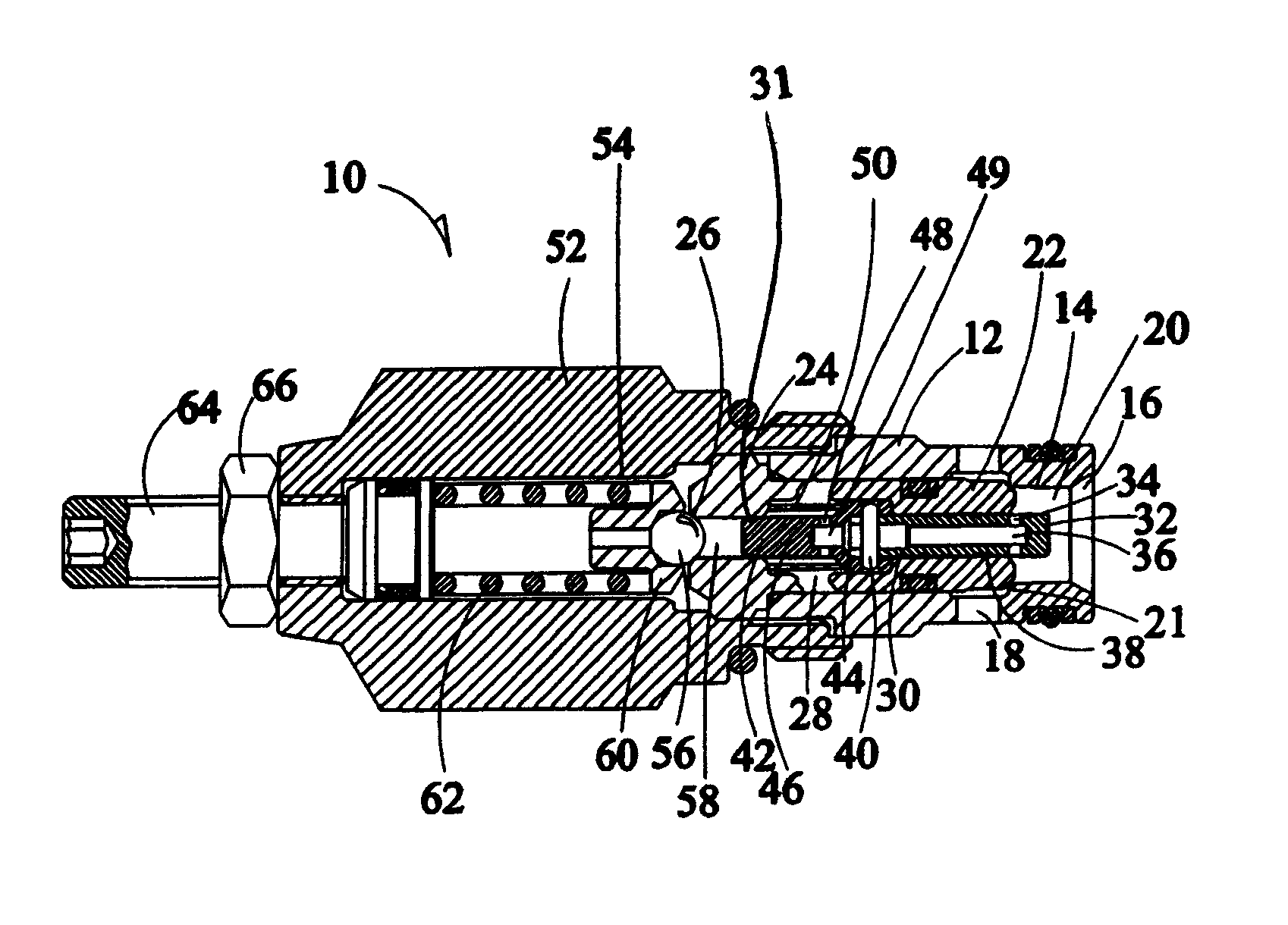
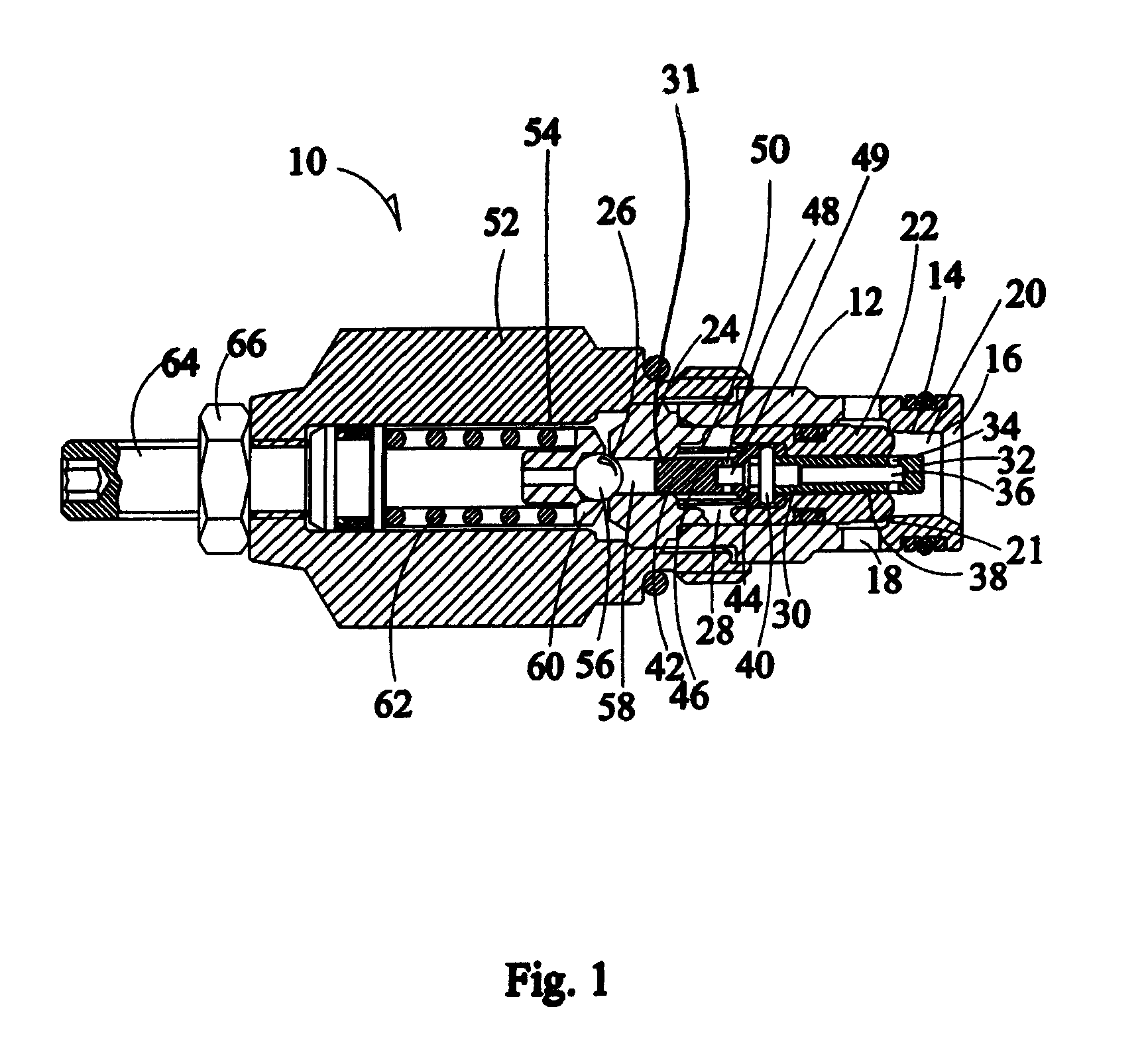
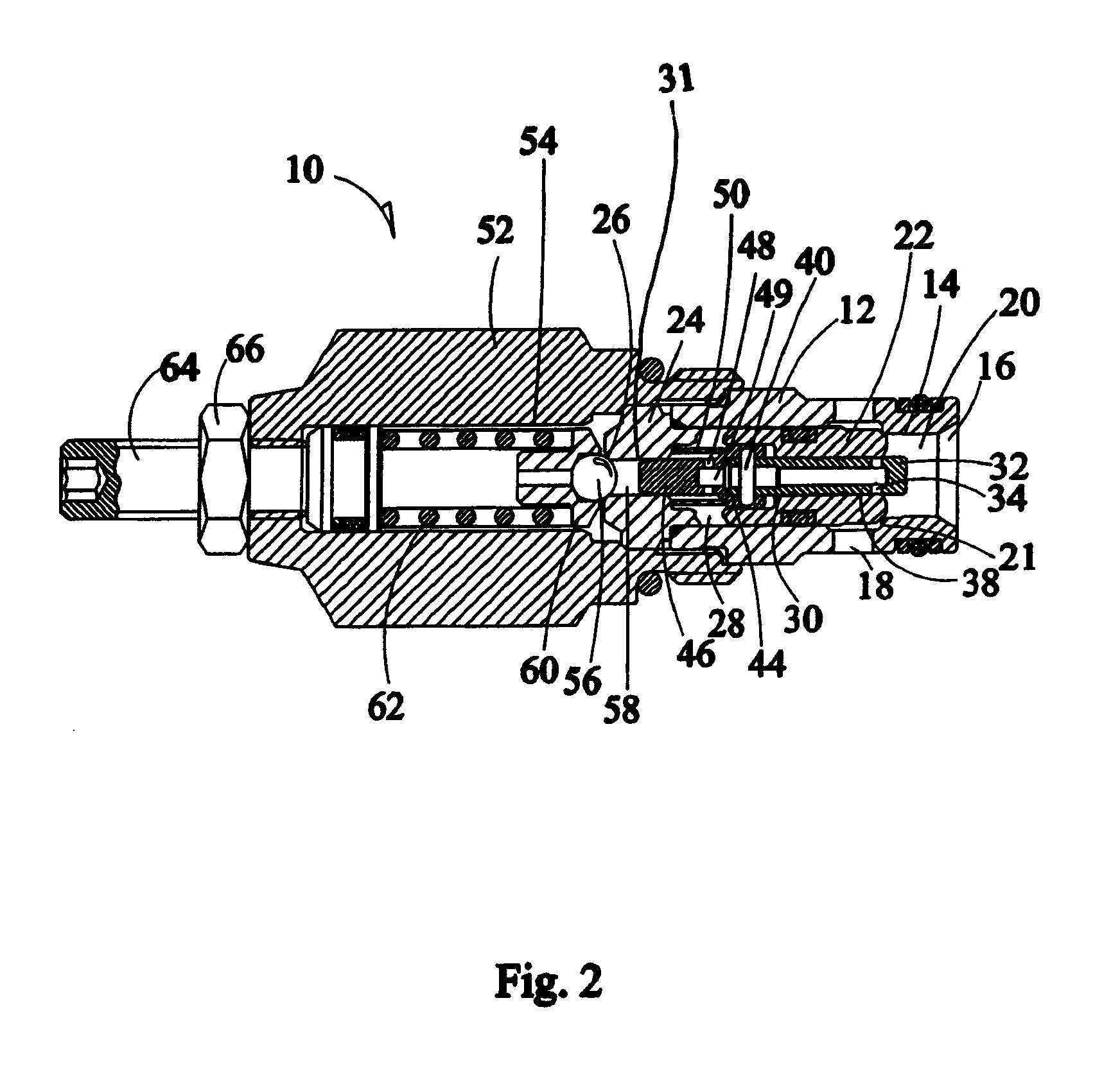
[0011]The figures show a relief valve 10. The relief valve 10 comprises a poppet housing 12 with a centrally located cavity 14 in fluid communication with a valve inlet 16 at a first end and a fluid outlet 18 adjacent the cavity 14 to provide fluid flow communication with a tank (not shown). Adjacent the inlet 16 within the cavity 14 is a first area 20 wherein the inlet 16 provides pressure. The poppet housing additionally has a poppet seat 21 therein for receiving a poppet 22.

[0012]Disposed within the cavity 14 is poppet 22 and a pilot 24 wherein the first end of the pilot matingly and detachably connects to the poppet 22 within cavity 14 as shown in FIGS. 1-3. The second end of the pilot forms a pilot seat 26 having a milled flat. A second area 28 is disposed between the poppet and pilot 22, 24 within cavity 14 of the poppet housing. The poppet 22 additionally has a cavity 30 disposed therein that extends the distance of the poppet 22. Similarly the pilot 24 has a cavity 31 dispos...


PUM


Abstract

A relief valve for a hydraulic machine that combines a poppet valve assembly and a pilot valve assembly together using a connector pin wherein internal fluid passageways within the poppet and pilot spools provide a fluid flow path between the inlet of the valve and a cavity disposed between the poppet and pilot. As a result of the internal passageways fluid is metered to the interior cavity to provide additional control and stability within the relief valve.

Description

BACKGROUND OF THE INVENTION[0001]This invention relates to hydraulic devices. More specifically this invention relates to a relief valve for a hydraulic device.[0002]Traditionally, low leakage relief valves utilize a direct acting poppet and low pressure rise rate valves are pilot operated. Direct acting poppet valves have a tendency to be unstable unless a very high rate spring or special geometry is used. The use of a high rate spring increases the pressure rise rate proportionately. Thus, there is a need to combine a poppet with a pilot to have functioning of both within a valve at a low cost. Attempts have been made to met this need; however, typically a traditional style pilot operation combined with a poppet is unstable. Additional problems exist with complex machining needed to accomplish the combination thus adding to manufacturing costs.[0003]Therefore, a principal object of the present invention is to provide a poppet relief valve that improves control of the valve.[0004]A...

Claims


Application Information

Patent Timeline
Patent Type & Authority Patents(United States)
IPC IPC(8): F16K31/122
CPCF16K15/044Y10T137/7758Y10T137/7762Y10T137/7769
Inventor COURTRIGHT, DENNIS O.SONCINI, ENZODAVOLI, DAVIDE I.
Owner DANFOSS POWER SOLUTIONS INC
Why Eureka
Try Eureka