Impregnator

Inactive Publication Date: 2013-01-08
CARBOTEK HLDG
View PDF10 Cites 14 Cited by
  • Summary
  • Abstract
  • Description
  • Claims
  • Application Information

AI Technical Summary

Benefits of technology

The invention aims to create an impregnator that can release gas effectively at low production and operating costs. This impregnator can be used in the food field, for making beer, and in a bar system. It improves the production of beer and other beverages.

Problems solved by technology

Besides known bubble-forming systems, such as agitation systems, loop reactors or injection systems, which are not very economical because of their vulnerability and in particular the high expense for equipment in injection systems (pressure vessel, pressure pump, cooling system) and the attendant high operating costs, carbonators or impregnators of the type defined at the outset have become established in the field of gassing beverages with carbonic acid in bars and pubs.
However, such impregnators are often used in inline gassing bar systems, in which the beverage precursor product is conventionally pumped out of a tank with piston pumps and more recently also from a bag using diaphragm pumps, so that the impregnator is exposed on the inlet side to the pressure surges of the piston pump, and a constant fuel pressure cannot be attained.
Especially in bar systems with a pressure gassing stage in the bar, in which systems a working pressure in the impregnator is required that is above the keg pressure that is usual in conventional bar systems, the problem arises that regulating the quantity is no longer readily possible at the dispensing tap.
The tap pressure, however, should be constant, since otherwise, if pressure fluctuations occur, an unwanted release of carbonic acid can occur.
Such tubular sieve carbonators, however, are not only relatively expensive in terms of material costs because of the high number of metal sieves but are also expensive with regard to the correspondingly complex assembly.
The surface area attainable with the bulk material, however, is still limited.
Nevertheless, clogging cannot be completely avoided over the course of time, and bulk material carbonators must therefore be replaced relatively often.
It is also disadvantageous that such bulk material carbonators are relatively difficult to clean, so that at the cleaning intervals necessary for reasons of food hygiene, especially in connection with beverages containing starch or sugar, usually the entire bulk material carbonator has to be replaced.

Method used


Image

  • Impregnator
  • Impregnator
  • Impregnator

Examples


Embodiment Construction

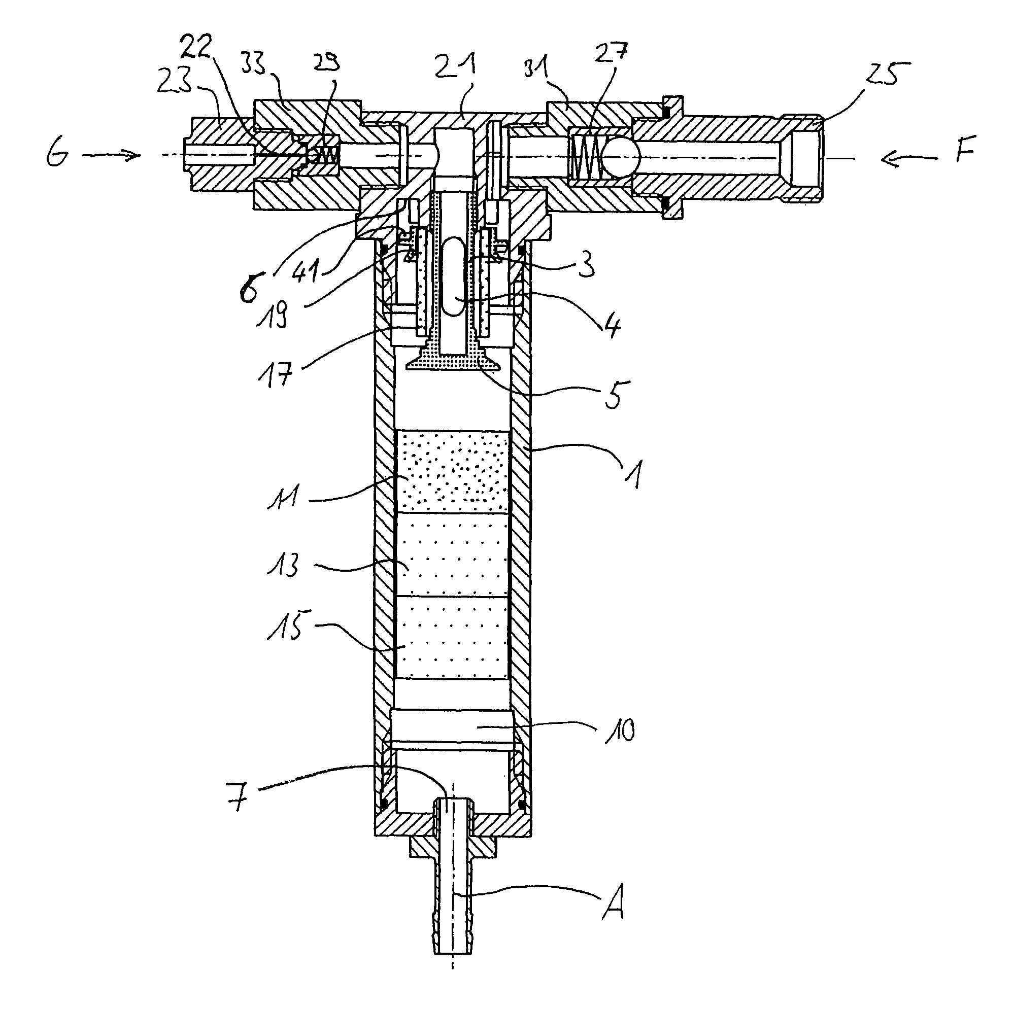
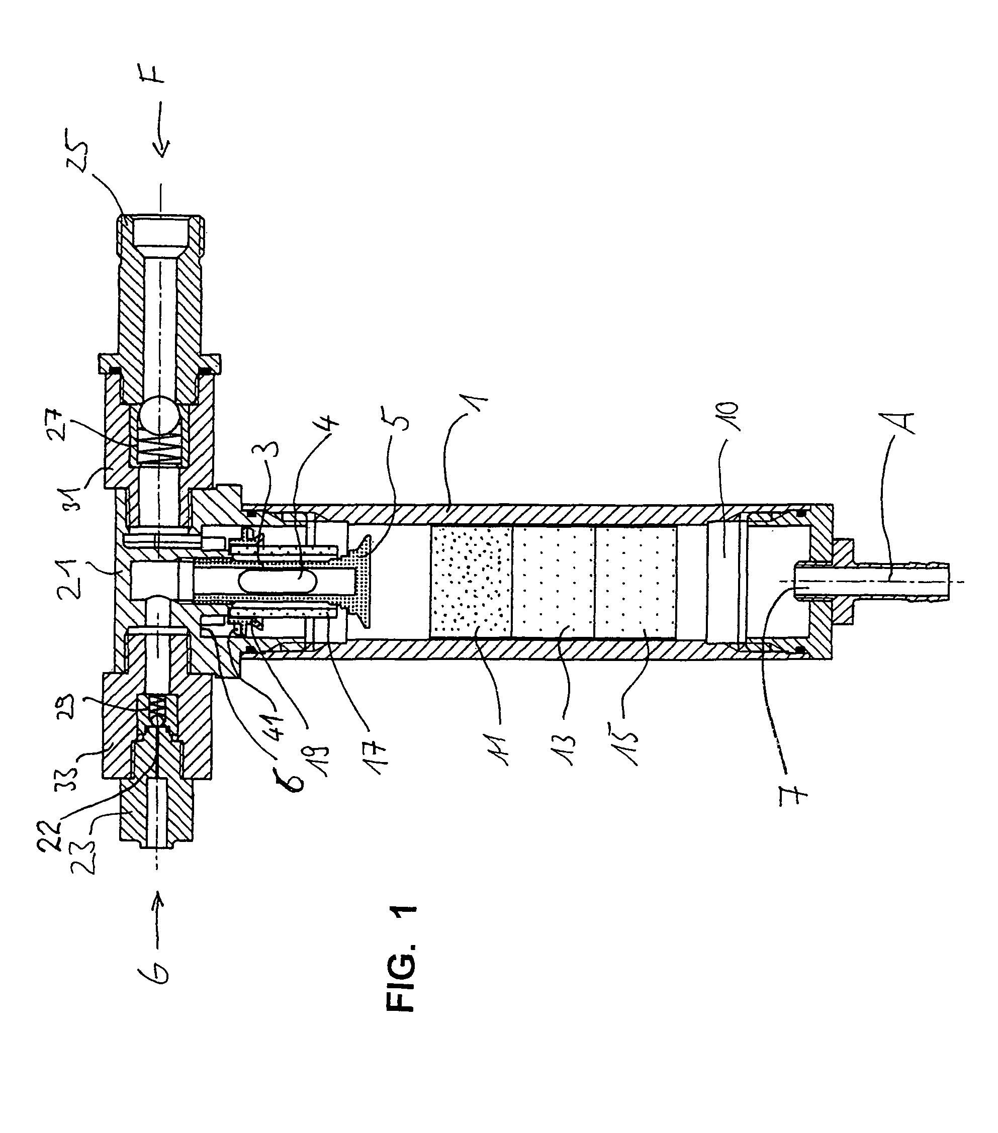
[0076]First, reference will be made to FIG. 1. Reference numeral 1 designates a tubular mixing cell. In the mixing cell 1, disklike impregnator bodies 11, 13, 15 are press-fitted in series and in succession, so that the liquid flowing through the mixing cell 1 and the gas, or the already premixed gas-liquid mixture, flowing through the mixing cell 1 must pass through the impregnator bodies 11, 13, 15 and thus enter into solution at the surface of the pores marked with dots. The first impregnator body 11 in order from the infeed side is made of a sintered material with finer pores than the two impregnator bodies 13, 15 that follow it.

[0077]The impregnator bodies are adjoined by a calming portion marked 10, in which the gas-liquid mixture emerging as a turbulent flow from the outlet-side impregnator body 15 is calmed to a laminar flow before exiting the impregnator through an outlet opening 7 and being conducted for instance to a dispensing tap in the dispenser system.

[0078]The outlet...


PUM

PropertyMeasurementUnit
Timeaaaaaaaaaa
Pressureaaaaaaaaaa
Diameteraaaaaaaaaa

Abstract

An impregnator for mixing a nonaerated or only slightly aerated liquid (F) with gas (G), in particular for mixing a noneffervescent or only slightly effervescent beer precursor product, or a beer precursor product containing CO2, with CO2, includes a mixing cell, in particular tubular, which except for an incoming liquid inlet, an incoming gas inlet, and an outlet, is partitioned off from the surrounding, and at least one Impregnator body is disposed in the mixing cell in such a way that the flow through the mixing cell of the liquid (F) and gas (G) must necessarily take place through the impregnator body. Disposed in the mixing cell is at least one impregnator body, which includes a porous solid body, namely of a foam material, a sponge, a follow fiber module, or a sintered material.

Description

BACKGROUND OF THE INVENTION[0001]1. Field of the Invention[0002]The invention relates to an impregnator for mixing a nonaerated or only slightly aerated liquid with a gas. The invention also relates to a pressure compensator assembly for bar systems, an impregnator for inline gassing bar systems, and a bar system with a pressure compensator assembly. The invention further relates to novel uses of such an impregnator. The nonaerated or only slightly aerated liquid may be a soda, soft drink, water, juice, or a low-carbon-dioxide or carbon-dioxide-free beer precursor product. The gas be carbon dioxide or nitrogen.[0003]2. Description of Related Art[0004]Impregnation in terms of the invention is the release of gases into liquids, or in other words impregnating liquids with gases, as it is carried out in absorption columns in large-scale chemical systems. For example, according to the German Patent DE 25 03 681, a gas is conducted from the bottom of a column to the top of the column in c...

Claims


Application Information

Patent Timeline
IPC IPC(8): B01F3/04
CPCB01F3/0446B01F3/04787B01F5/0451B01F5/0691B01F15/0433Y10T137/7837B01F23/232B01F23/236B01F25/3131B01F25/4522B01F35/8331B67D1/0059
Inventor FISCHER, GEORG
Owner CARBOTEK HLDG
Why Eureka
Try Eureka