Self locking trailer hitch
- Summary
- Abstract
- Description
- Claims
- Application Information
AI Technical Summary
Benefits of technology
Problems solved by technology
Method used
Image
Examples
Embodiment Construction
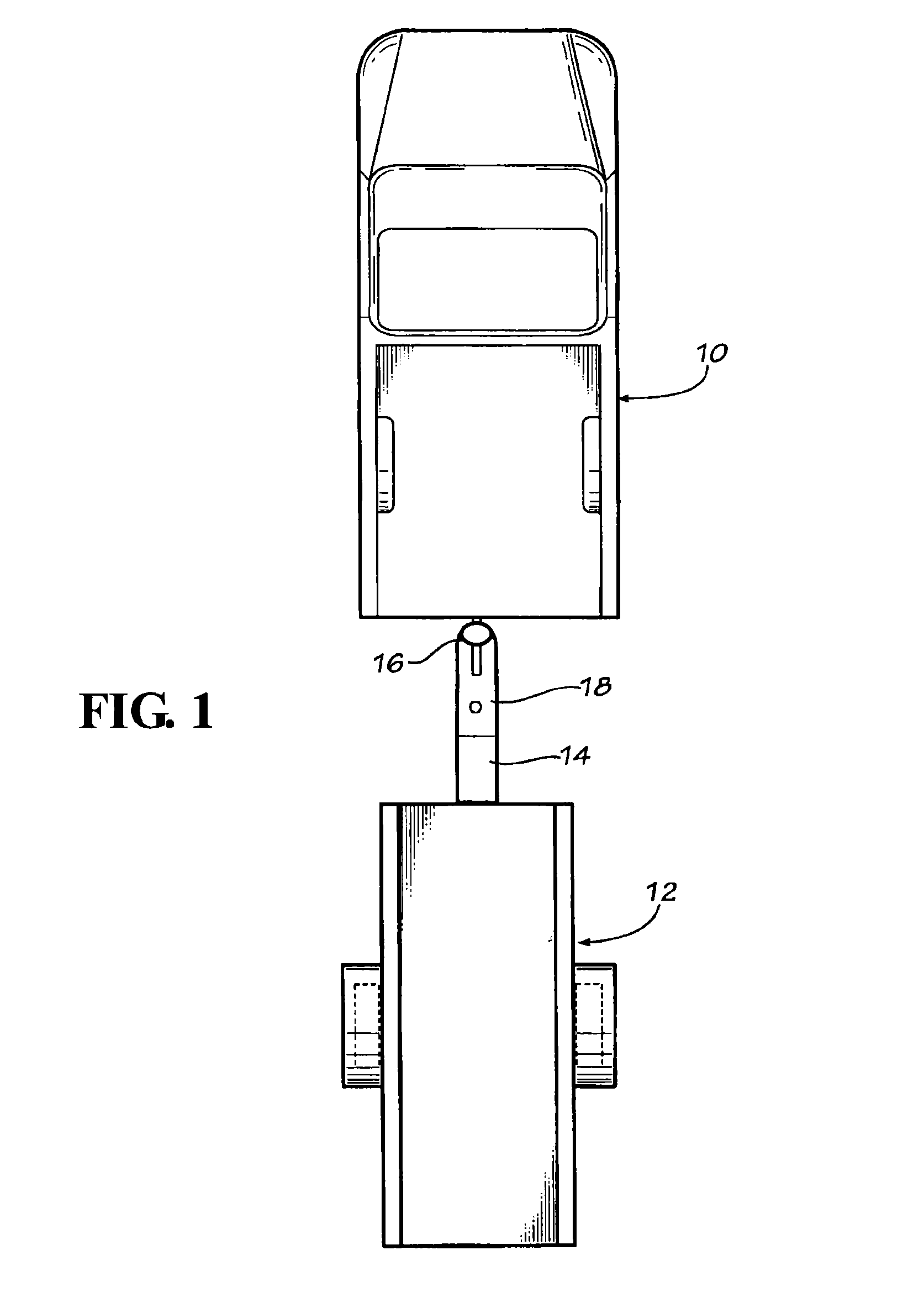
[0024]Referring now in more detail to the drawings, in which like numerals indicate like parts throughout the several views, FIG. 1 illustrates a towing vehicle, such as a pickup truck 10 and a trailer 12 that includes a draft draw bar 14 extending between the trailer and the towing vehicle, and a trailer hitch 16 mounted on the front end of the draw bar 14 that engages a conventional hitch ball mounted to the rear of the towing vehicle 10.
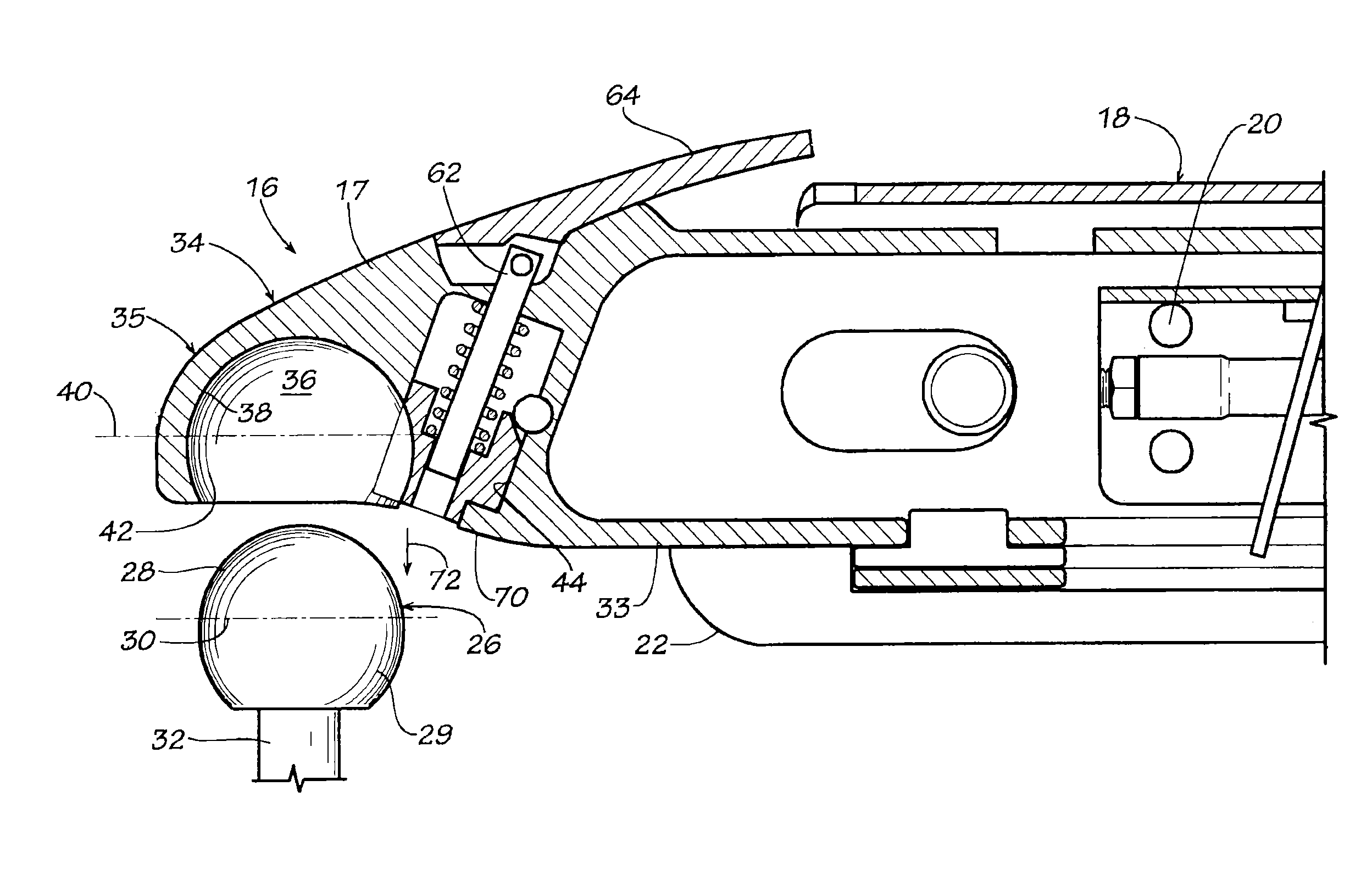
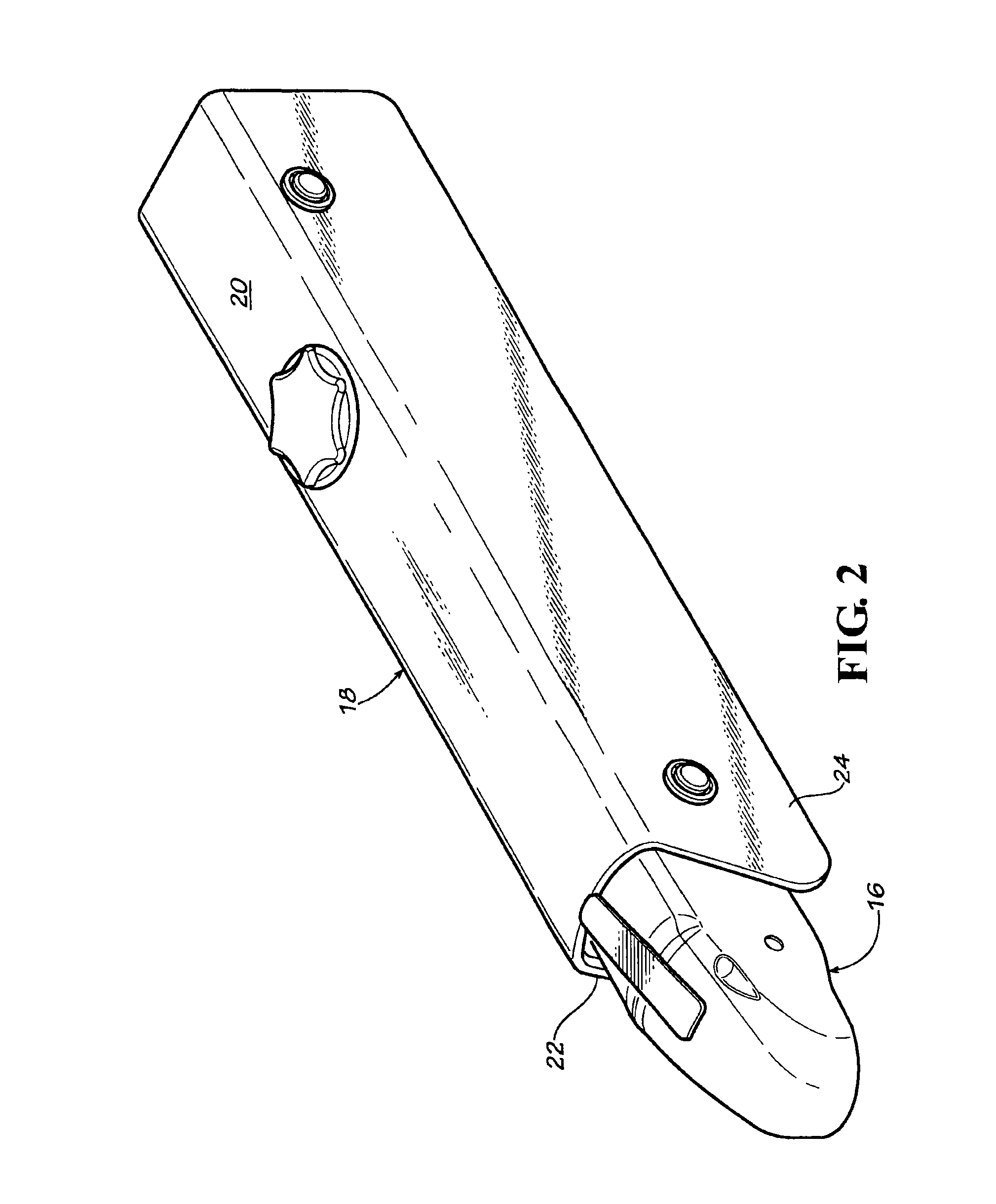
[0025]Trailer hitch 16 is shown in more detail in FIGS. 2 and 3 of the drawings. As shown in FIG. 2, the trailer hitch 16 includes a mounting sleeve 18 that is mounted to the forward end of the draw bar 14. The mounting sleeve typically will be formed in an inverted U-shape, with a horizontal top wall 20 and opposed vertically oriented side walls 22 and 24. Mounting sleeve 18 supports at its forward end the trailer hitch 16 and also supports the brake cylinders, electrical wiring and other components not further described herein.
[0026]As shown in ...
PUM
 Abstract
Description
Claims
Application Information
 - R&D
- Intellectual Property
- Life Sciences
- Materials
- Tech Scout
- Unparalleled Data Quality
- Higher Quality Content
- 60% Fewer Hallucinations
Browse by: Latest US Patents, China's latest patents, Technical Efficacy Thesaurus, Application Domain, Technology Topic, Popular Technical Reports.
© 2025 PatSnap. All rights reserved.Legal|Privacy policy|Modern Slavery Act Transparency Statement|Sitemap|About US| Contact US: help@patsnap.com


