
Structure for an electromagnetic machine having compression and tension members

a technology of tension member and structure, applied in the field of electronic machines, can solve the problems of reducing affecting the performance of the structure, and affecting the operation of the structure, so as to increase the structural efficiency of the structure and increase the resistance of the structure to deflection.

Inactive Publication Date: 2012-12-25
BWP GRP
View PDF21 Cites 17 Cited by
  • Summary
  • Abstract
  • Description
  • Claims
  • Application Information

AI Technical Summary

Benefits of technology

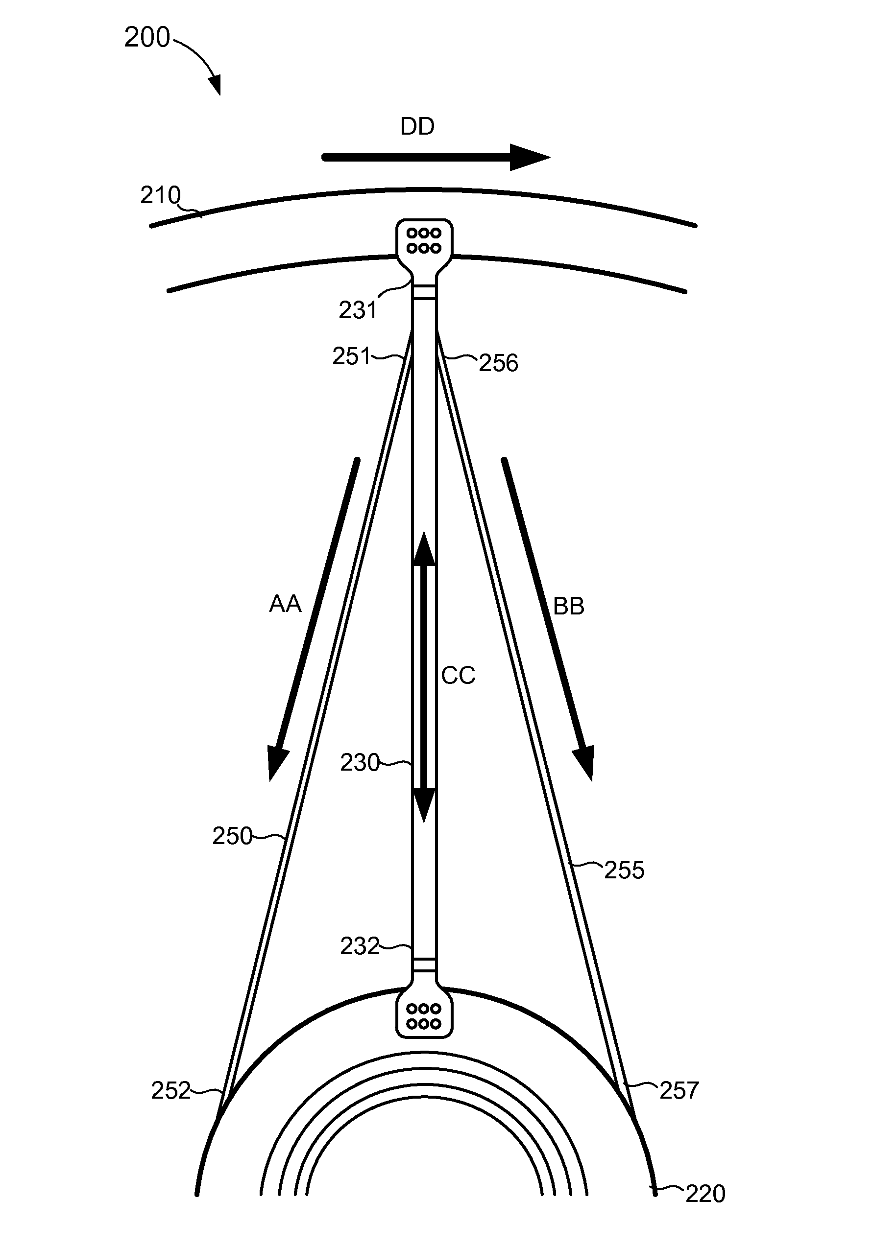
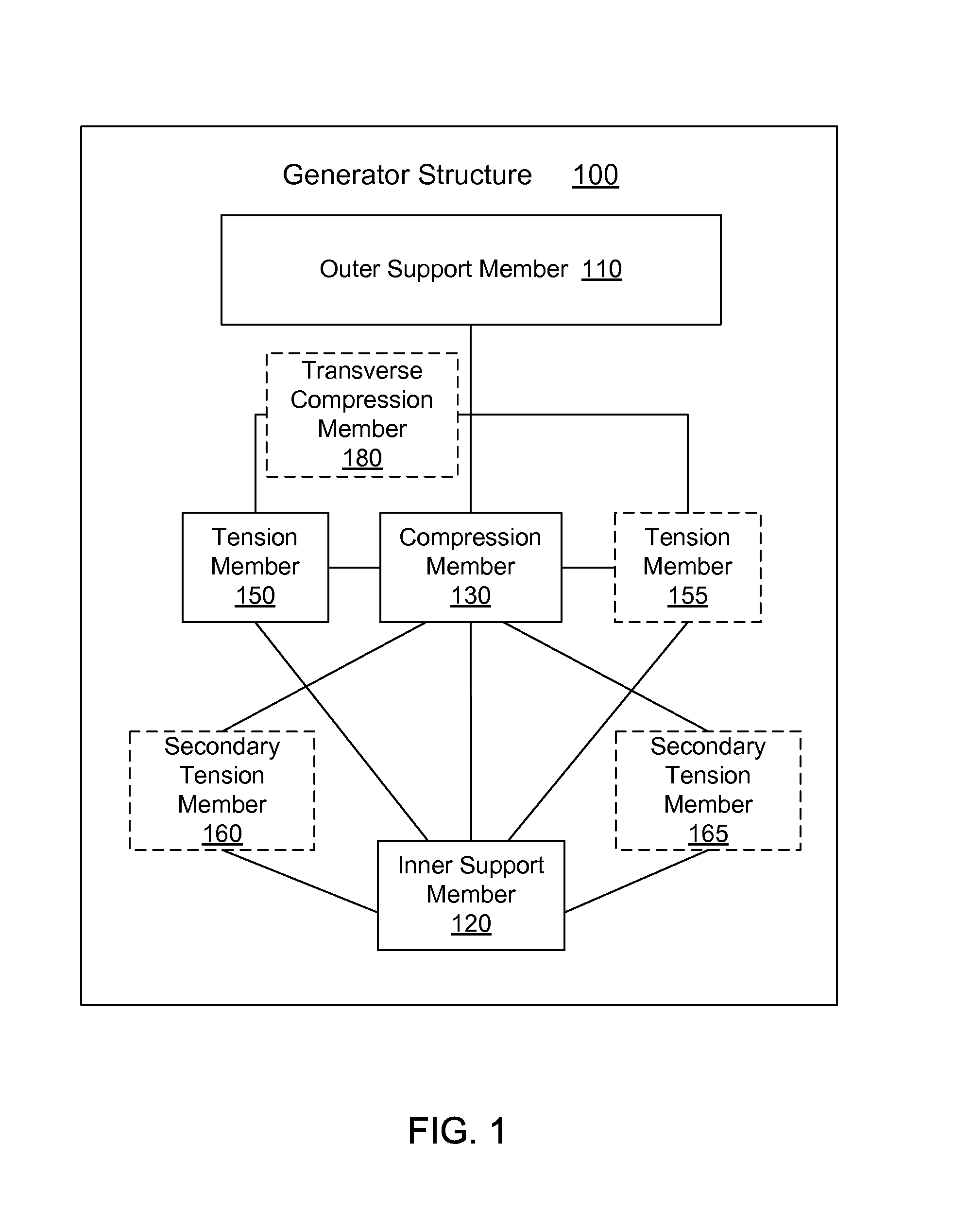
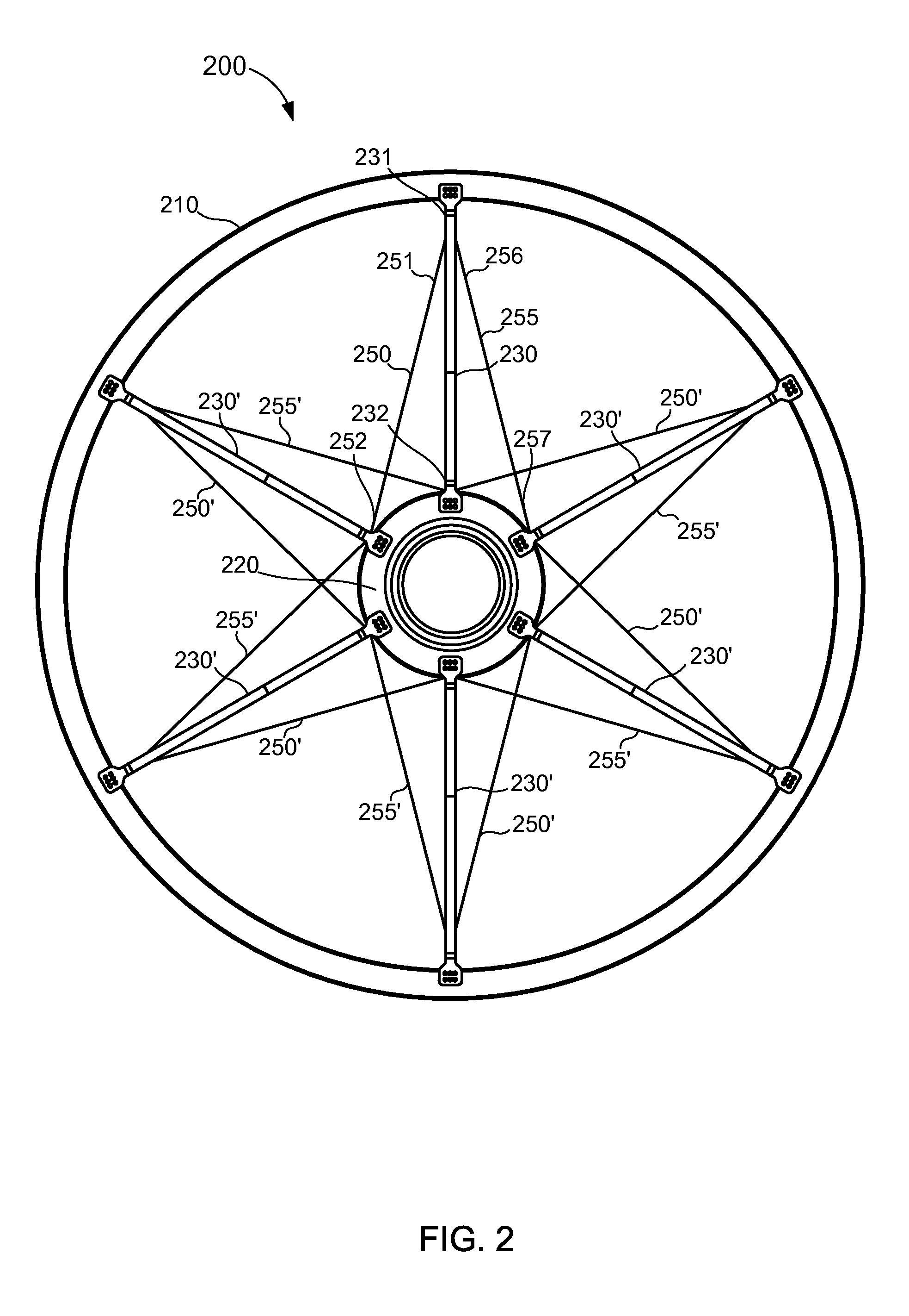
[0007]Apparatus and methods for increasing the structural efficiency of a structure in an electromagnetic machine and / or increasing the structures resistance to deflection are described herein. In some embodiments, a structure included in an electromagnetic machine includes an outer support member configured to support one of a conductive winding or a magnet. The structure further includes an inner support member, a first elongate compression member, a second elongate compression member, and an elongate tension member. The first elongate compression member and the second elongate compression member each include a first end portion coupled to the outer support member and a second end portion coupled to the inner support member and can resist radial and axial deflection of the outer support member relative inner support member. The elongate tension member includes a first end portion coupled to a portion of the first compression member and a second end portion coupled to the inner support or the second elongate compression member and can resist rotational deflection of the outer support member relative to the inner support member.

Problems solved by technology

Such machines are generally the lowest cost and lightest weight permanent magnet machines, but they typically suffer from limitations in performance that can be traced to a variety of design concerns.
Significant violations of air gap size, such as where the air gap is nearly closed or is closed altogether, can be dangerous or destructive to equipment and personnel, particularly if the air gap is compromised during operation of the electromagnetic machine.
As the size of an electromagnetic machine increases (e.g., as known in wind power generation), dependence on structural stiffness to ensure that a minimum air gap clearance is maintained can become costly and / or can affect the overall efficiency of the machine due to the weight of the required structure.

Method used


Image

  • Structure for an electromagnetic machine having compression and tension members
  • Structure for an electromagnetic machine having compression and tension members
  • Structure for an electromagnetic machine having compression and tension members

Examples


Embodiment Construction

[0019]Apparatus and methods for increasing the structural efficiency of a structure in an electromagnetic machine and / or increasing the structure's resistance to deflection are described herein. For example, the structural efficiency can be increased by controlling and balancing the stiffness and / or mass of the various components of an electromagnetic machine. In some embodiments, a structure included in an electromagnetic machine includes an outer support member configured to support a conductive winding or a magnet. The structure further includes an inner support member, a first elongate compression member, a second elongate compression member, and an elongate tension member. The first elongate compression member and the second elongate compression member each include a first end portion coupled to the outer support member and a second end portion coupled to the inner support member and can resist radial and axial deflection of the outer support member relative inner support membe...


PUM


Abstract

A structure of an electromagnetic machine includes an outer support member configured to support a conductive winding or a magnet. The structure further includes an inner support member, a first elongate compression member, a second elongate compression member, and an elongate tension member. The first elongate compression member and the second elongate compression member each include a first end portion coupled to the outer support member and a second end portion coupled to the inner support member to resist radial and axial deflection of the outer support member relative inner support member. The elongate tension member includes a first end portion coupled to the first compression member and a second end portion coupled to one of the inner support or the second elongate compression member to resist rotational deflection of the outer support member relative to the inner support member.

Description

BACKGROUND[0001]Some embodiments described herein relate to electromagnetic machines and more particularly to structures for an electronic machine having tension and compression components.[0002]Permanent magnet electromagnetic machines (referred to as “permanent magnet machines” or electromagnetic machines” herein) utilize magnetic flux from permanent magnets to convert mechanical energy to electrical energy or vice versa. Various types of permanent magnet machines are known, including axial flux machines, radial flux machines, and transverse flux machines, in which one component rotates about an axis or translates along an axis, either in a single direction or in two directions (e.g., reciprocating, with respect to another component). Such machines typically include windings to carry electric current through coils that interact with the flux from the magnets through relative movement between the magnets and the windings. In a common industrial application arrangement, the permanen...

Claims


Application Information

Patent Timeline
Patent Type & Authority Patents(United States)
IPC IPC(8): H02K1/30H02K1/22
CPCH02K1/187H02K1/30H02K7/1838
Inventor OYAGUE, FRANCISCO JAVIER
Owner BWP GRP
Learn More