
Paper feeding mechanism

a paper feeding mechanism and paper feeding technology, applied in the field of paper feeding mechanism, can solve the problems of increasing the time interval between, reducing the paper feeding speed, increasing the cost of electricity and components of the paper feeding mechanism, etc., and achieves the effects of reducing space, saving paper feeding time, and improving paper feeding speed

Inactive Publication Date: 2012-12-25
FOXLINK IMAGE TECH
View PDF3 Cites 2 Cited by
  • Summary
  • Abstract
  • Description
  • Claims
  • Application Information

AI Technical Summary

Benefits of technology

[0007]As described above, the paper feeding mechanism depends on the one-way clutch mechanism being rotatably mounted to the shell to realize the transporting motor to synchronously drive the transporting gear and the separation wheel to rotate continuously. As a result, paper feeding time is saved to decrease a space between each two pieces of the papers fed to the paper feeding mechanism so as to improve a paper feeding speed. Therefore, the paper feeding mechanism uses fewer components to design a proper structure to realize a better working performance.

Problems solved by technology

Furthermore, the separation wheel 82 will cause a time delay from restarting to accelerating the pickup motor 81 that further increases the time interval between each two pieces of papers fed to the paper feeding mechanism and lowers a paper feeding speed.
Moreover, if another driving motor is specially used to drive the separation wheel 82, cost of electricity and components of the paper feeding mechanism will increase, and the paper feeding mechanism will occupy a larger space in the office equipment.

Method used


Image

  • Paper feeding mechanism
  • Paper feeding mechanism
  • Paper feeding mechanism

Examples


Embodiment Construction

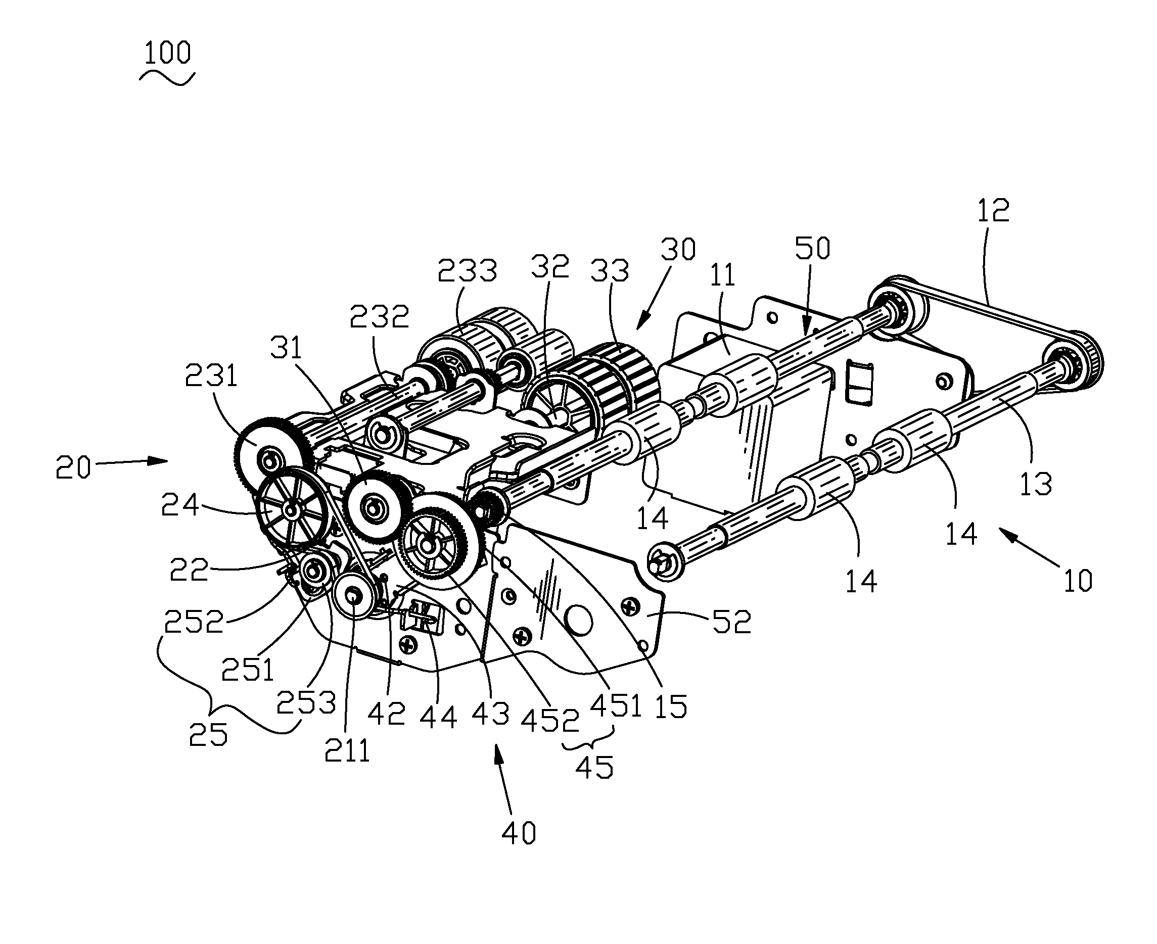
[0017]With reference to FIG. 1 and FIG. 3, an embodiment of a paper feeding mechanism 100 which is used in a scanner (not shown) or a multi-functional peripheral (not shown) in accordance with the present invention is shown. The paper feeding mechanism 100 mounted in a shell 50 includes a transporting mechanism 10, a pickup mechanism 20, a separation mechanism 30 and a one-way clutch mechanism 40. The shell 50 includes a first shell 51 disposed in a front of the paper feeding mechanism 100, and a second shell 52 disposed in a rear of the paper feeding mechanism 100.

[0018]Referring to FIG. 1 and FIG. 2, the transporting mechanism 10 mounted to the shell 50 includes a transporting motor 11, a transporting conveyer 12 driven by the transporting motor 11, a pair of transporting rollers 13 driven by the transporting conveyer 12, a plurality of transporting wheels 14 mounted around the transporting rollers 13, a transporting gear 15 mounted to one end of the transporting roller 13, and a ...


PUM


Abstract

A paper feeding mechanism mounted to a shell includes a pickup mechanism, a transporting mechanism, a separation mechanism and a one-way clutch mechanism. The pickup mechanism includes a pickup motor having a rotating roller, a pickup roller and a pickup wheel. The transporting mechanism includes a transporting motor, a transporting roller, a transporting wheel and a transporting gear. The separation mechanism includes a separation roller, a separation gear and a separation wheel. The one-way clutch mechanism includes a one-way axle, a wiggling arm, a restoration elastic element fastened between the wiggling arm and the shell, and a releasing gear. The one-way axle passes through one end of the wiggling arm. The rotating roller of the pickup motor passes through the one-way axle. The releasing gear mounted to the other end of the wiggling arm is engaged with the transporting gear and the separation gear.

Description

BACKGROUND OF THE INVENTION[0001]1. Field of the Invention[0002]The present invention generally relates to a paper feeding mechanism, and more particularly to a paper feeding mechanism capable of improving a paper feeding speed.[0003]2. The Related Art[0004]Referring to FIG. 8, a paper feeding mechanism used in an office equipment, such as a scanner or a multi-functional peripheral, generally includes a transporting mechanism and a pickup mechanism. The transporting mechanism includes a transporting motor 71, and a plurality of transporting wheels 72 driven by the transporting motor 71. The pickup mechanism includes a pickup motor 81, a separation wheel 82 and a pickup wheel 83 driven by the pickup motor 81. When a piece of paper needs to be fed into the office equipment, if there is no paper located under the pickup wheel 83, the pickup motor 81 drives the pickup wheel 83 to pick up papers, and then drives the separation wheel 82 to separate the papers into the transporting mechani...

Claims


Application Information

Patent Timeline
Patent Type & Authority Patents(United States)
IPC IPC(8): B65H5/00
CPCB65H3/0669B65H2403/421B65H2403/422B65H2403/72B65H2403/942B65H2801/06
Inventor LIAO, CHING-FENGCHEN, YUNG-KAILIAO, WEN-CHING
Owner FOXLINK IMAGE TECH
Learn More