
Flow limiting bottle cap

a bottle cap and flow limit technology, applied in the field of beverage container closures, can solve the problems of containers with other fluids, difficulties, and risk of spillage for the unwary, and achieve the effect of low manufacturing cost and low sale pri

Inactive Publication Date: 2012-12-25
GRIFFIN DAVID L
View PDF3 Cites 2 Cited by
  • Summary
  • Abstract
  • Description
  • Claims
  • Application Information

AI Technical Summary

Benefits of technology

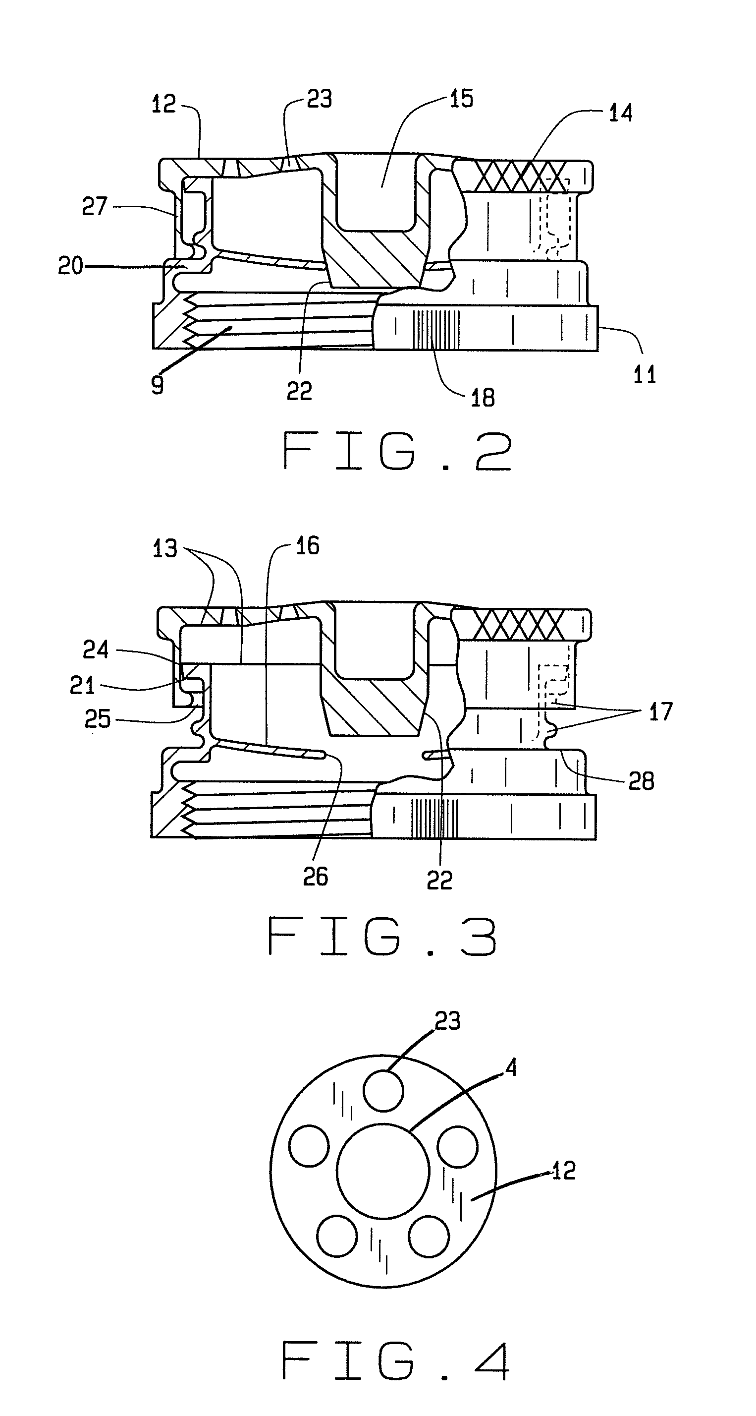
[0010]Generally, the present invention is a two-piece bottle cap designed to fit a milk or other beverage container. The cap includes two portions and easily attaches upon the existing external threads of the container. The cap has a quick sealing feature from a truncated conical member inserted into a circular hole in a semi-flexible membrane. More particularly, the cap has its upper member with a plurality of conically shaped holes therein where the holes produce a laminar produce a laminar flow of fluid outwardly from the beverage container when tipped. The holes also have an edge condition that ceases flow of fluid promptly as the container moves into an upright orientation.
[0017]Another object is to provide such a cap that has a low cost of manufacture with regard to both materials and labor, and which accordingly then has a low sale price to the milk packagers and then to the consuming public.

Problems solved by technology

However, these push pull caps permit a gush of fluid to exit the container with the risk of spillage for the unwary.
Though containers for beverages are described, containers of other fluids where a gush of fluid causes difficulties are also foreseen.

Method used


Image

  • Flow limiting bottle cap
  • Flow limiting bottle cap
  • Flow limiting bottle cap

Examples


Embodiment Construction

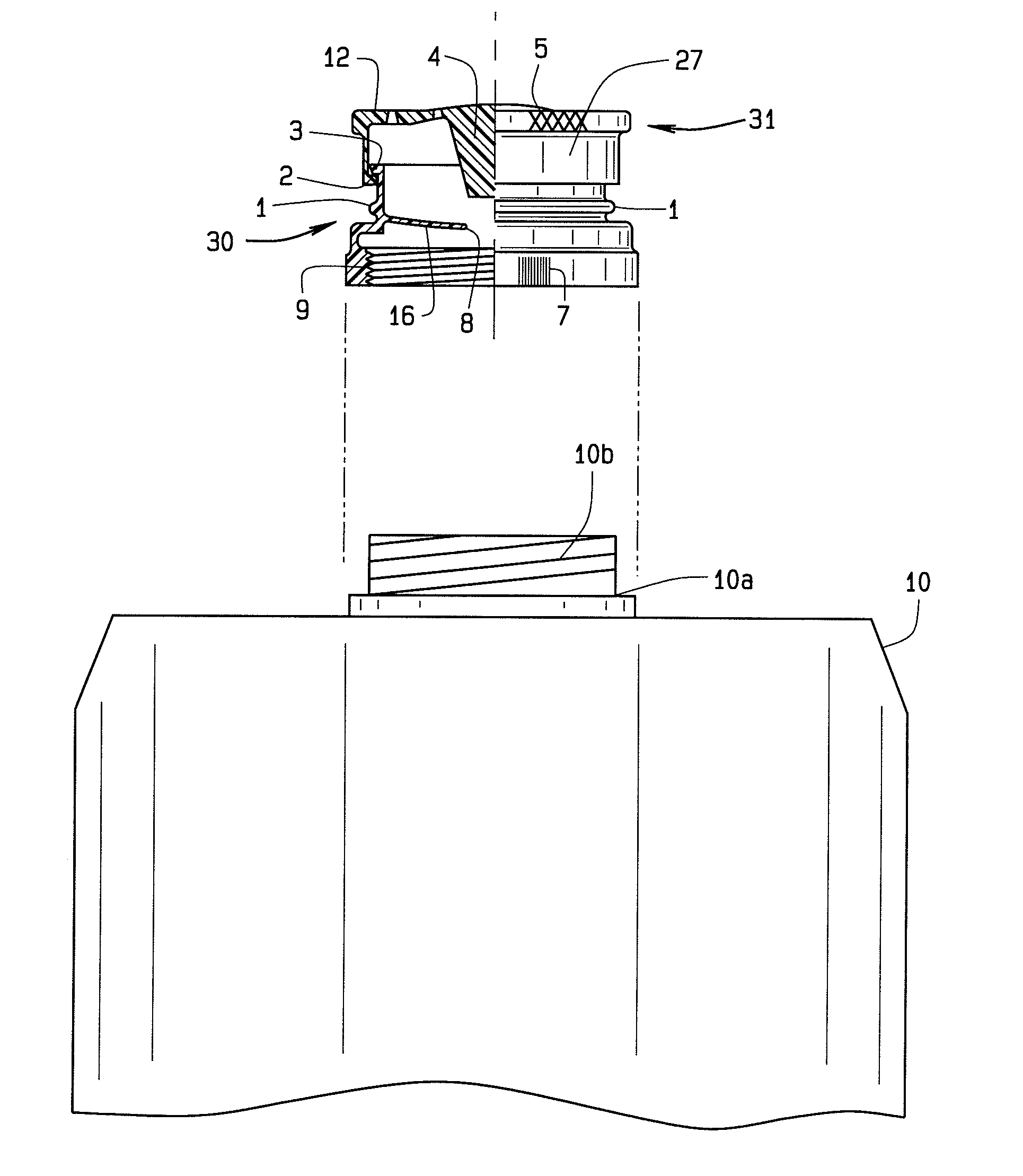
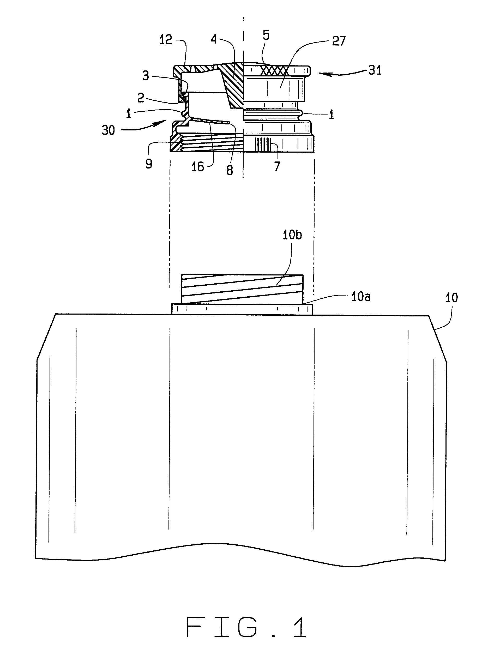
[0030]The present invention overcomes the prior art limitations and provides a flow limiting bottle cap for use upon beverage containers, primarily milk jugs. FIG. 1 shows the present invention ready for securement upon a container 10. The present invention connects to a neck 10a extending from the uppermost portion of the container. The neck has generally external threads as at 10b. The invention generally substitutes with the original closure cap found on either a half or a full gallon jug of milk in a plastic bottle. After purchasing the milk, the supplied cap and security seal, if present, are removed by the customer. The customer may or may not retain the supplied cap for reuse in the absence of the invention. The cap of the invention generally screws upon the external threads, as at 10b, upon the beverage container in place of the original cap.

[0031]The cap has a lower portion 30 and a concentric upper portion 31. The lower portion engages the neck 10a of the container and the...


PUM


Abstract

The flow limiting bottle cap secures to a container having a threaded neck and allows a user to select an open or a closed position without removing the cap from a container. Additionally fluid from within a container, when poured, forms multiple separate streams in laminar flow. The cap provides a pattern of conically shaped holes for passing of fluid. Each hole has edge conditions for adjusting the flow relative to pouring. The cap opens by raising an upper portion and closes by lowering the upper portion or by rotating the upper portion to expose the holes and closing by rotating oppositely to block the holes. Knurling upon the perimeter of the upper portion aids the user. An internal seal also excludes atmospheric communication to reduce spoilage of fluids within a container.

Description

CROSS REFERENCE TO RELATED APPLICATIONS[0001]This non-provisional application is filed as a continuation in part of the non-provisional application Ser. No. 12 / 154,925 with a filing date of May 28, 2008 now abandoned which was filed as a response to a petition to revive application Ser. No. 09 / 288,739 and claims priority to the continuation in part application Ser. No. 09 / 288,739 filed Apr. 7, 1999 now abandoned under petition for revival, which claims priority to the continuation in part application Ser. No. 09 / 284,345 filed Apr. 14, 1999, now U.S. Pat. No. 6,129,295, and the continuation in part application Ser. No. 09 / 537,163 filed Mar. 27, 2000 which has been merged into the continuation in part application Ser. No. 09 / 288,739 which claims priority to the non-provisional application Ser. No. 09 / 034,757 filed Mar. 4, 1998, now abandoned and this non-provisional application claims priority to the non-provisional application Ser. No. 11 / 402,673 filed Apr. 13, 2006, now abandoned.BA...

Claims


Application Information

Patent Timeline
Patent Type & Authority Patents(United States)
IPC IPC(8): B67D3/00
CPCB65D47/246B65D47/247
Inventor GRIFFIN, DAVID L.
Owner GRIFFIN DAVID L
Learn More