Eureka AIR delivers breakthrough ideas for toughest innovation challenges, trusted by R&D personnel around the world.

Mechanical resonator optimization using shear wave damping

a mechanical resonator and damping technology, applied in the field of biometrics, can solve the problem that the accuracy of the measurement output data of systems is inherently limited

Active Publication Date: 2012-12-18
SONAVATION INC
View PDF2 Cites 82 Cited by
  • Summary
  • Abstract
  • Description
  • Claims
  • Application Information

AI Technical Summary

Problems solved by technology

When constructing a sensing system that incorporates, for example, one of the modalities noted above, designers must consider not only contrast ratio, but manufacturability, along with costs.
That is, under ideal conditions and with the utmost care and consideration during design and / or manufacturing, these systems are inherently limited in the accuracy of their measurement output data.

Method used


Image

  • Mechanical resonator optimization using shear wave damping
  • Mechanical resonator optimization using shear wave damping
  • Mechanical resonator optimization using shear wave damping

Examples


Embodiment Construction

[0026]The following detailed description of the present invention refers to the accompanying drawings that illustrate exemplary embodiments consistent with this invention. Other embodiments are possible, and modifications may be made to the embodiments within the spirit and scope of the invention. Therefore, the following detailed description is not meant to limit the invention. Rather, the scope of the invention is defined by the appending claims.

[0027]It will be apparent to one skilled in the art that the present invention, as described below, may be implemented in many different embodiments. Any actual software code implementing the present invention is not limiting of the present invention. Thus, the operational behavior of the present invention will be described with the understanding that modifications and variations of the embodiments are possible, given the level of detail presented herein.

Advantages of Acoustic Impediography Sensing

[0028]As noted above, the present inventio...


PUM


Abstract

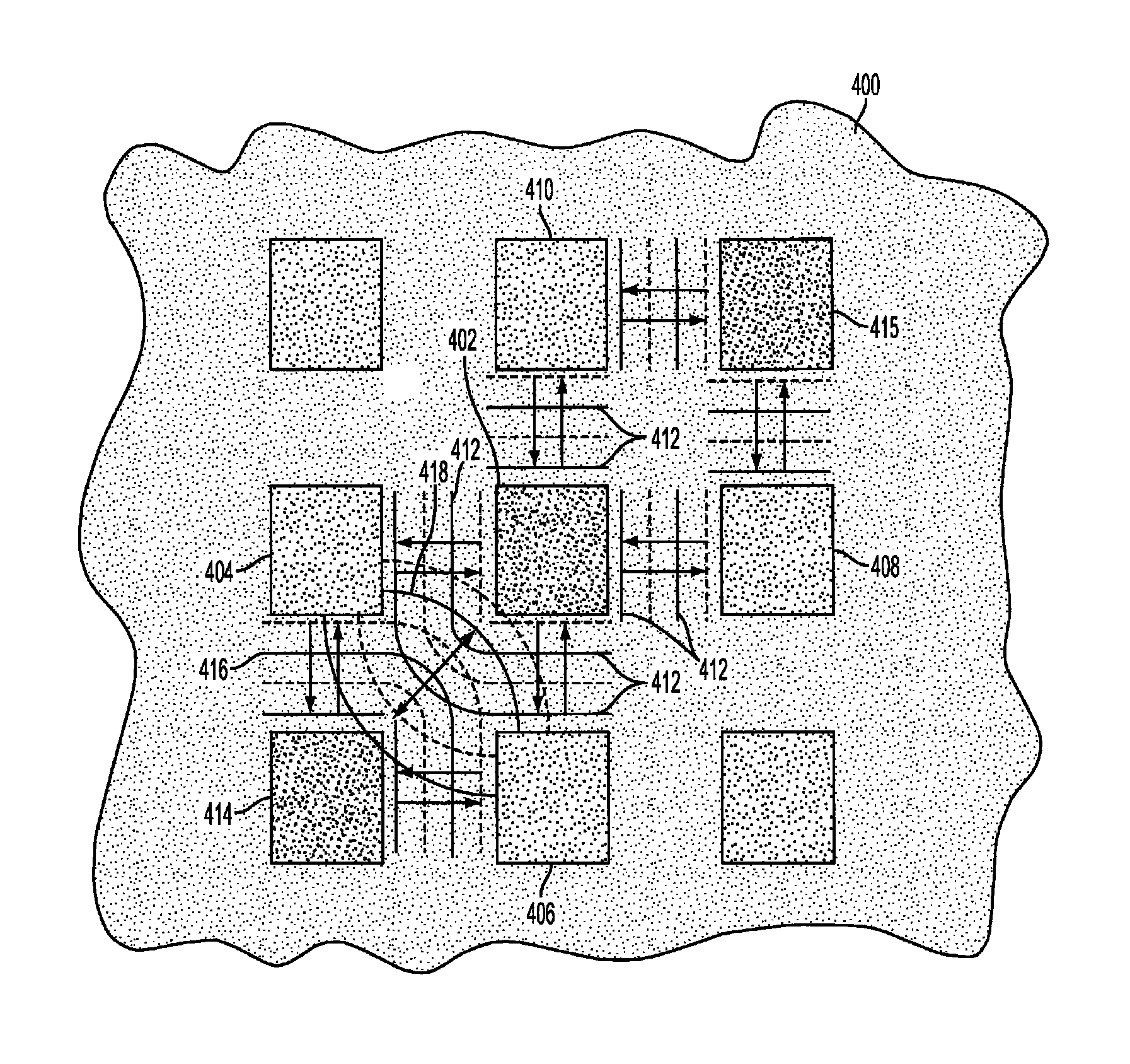
Provided is a fingerprint sensor including one or more mechanical devices for capturing the fingerprint. The mechanical devices include a matrix of pillars and are configured to be mechanically damped based upon an applied load. A q factor of the pillars is optimized by adjusting a distance between pillars within the matrix in accordance with a quarter shear wavelength at an operating wavelength.

Description

BACKGROUND OF THE INVENTION[0001]1. Field of the Invention[0002]The present invention generally relates to biometrics.[0003]2. Related Art[0004]A variety of well known techniques exist for sensing, measuring, and identifying biometric characteristics. These techniques focus on unique characteristics associated with structures that form the biometrics. By way of example, fingerprints, defined by ridges and valleys in a finger, are one such biometric.[0005]As known to those of skill in the art, fingerprints are defined by unique structures on the surface of the finger called ridges and valleys. These ridges and valleys can be sensed, measured, and identified based upon a number of different modalities.[0006]For example, some fingerprint measurement modalities rely on density values associated with the ridges and valleys. Others rely on dielectric permittivity as measured when an electric current if passed through the ridges and valleys. With respect to dielectric permittivity for exam...

Claims


Application Information

Patent Timeline
Patent Type & Authority Patents(United States)
IPC IPC(8): G06K9/00
CPCG06K9/0002G06V40/1306
Inventor SCHMITT, RAINER M.
Owner SONAVATION INC
Why Eureka
Eureka Blog
Learn More