
X-ray irradiator

a technology of x-ray irradiator and x-ray tube, which is applied in the direction of x-ray tube structural circuit elements, basic electric elements, electric discharge tubes, etc., can solve the problems of difficult to deal with these connectors, and achieve the effects of reducing the size of the x-ray irradiator, preventing the occurrence of discharge, and reducing the difference in electric potential

Inactive Publication Date: 2012-12-11
JOB CORP
View PDF8 Cites 6 Cited by
  • Summary
  • Abstract
  • Description
  • Claims
  • Application Information

AI Technical Summary

Benefits of technology

The technical effect of this patent is to provide an X-ray irradiator that reduces the occurrence of discharge caused by differences in electric potential, while also being smaller and lighter than conventional X-ray irradiators.

Problems solved by technology

Thus, it has been difficult to deal with these connectors.

Method used


Image

  • X-ray irradiator
  • X-ray irradiator
  • X-ray irradiator

Examples


Embodiment Construction

[0035]Descriptions will be hereinbelow provided for the present invention, referring its embodiment as shown in the drawings.

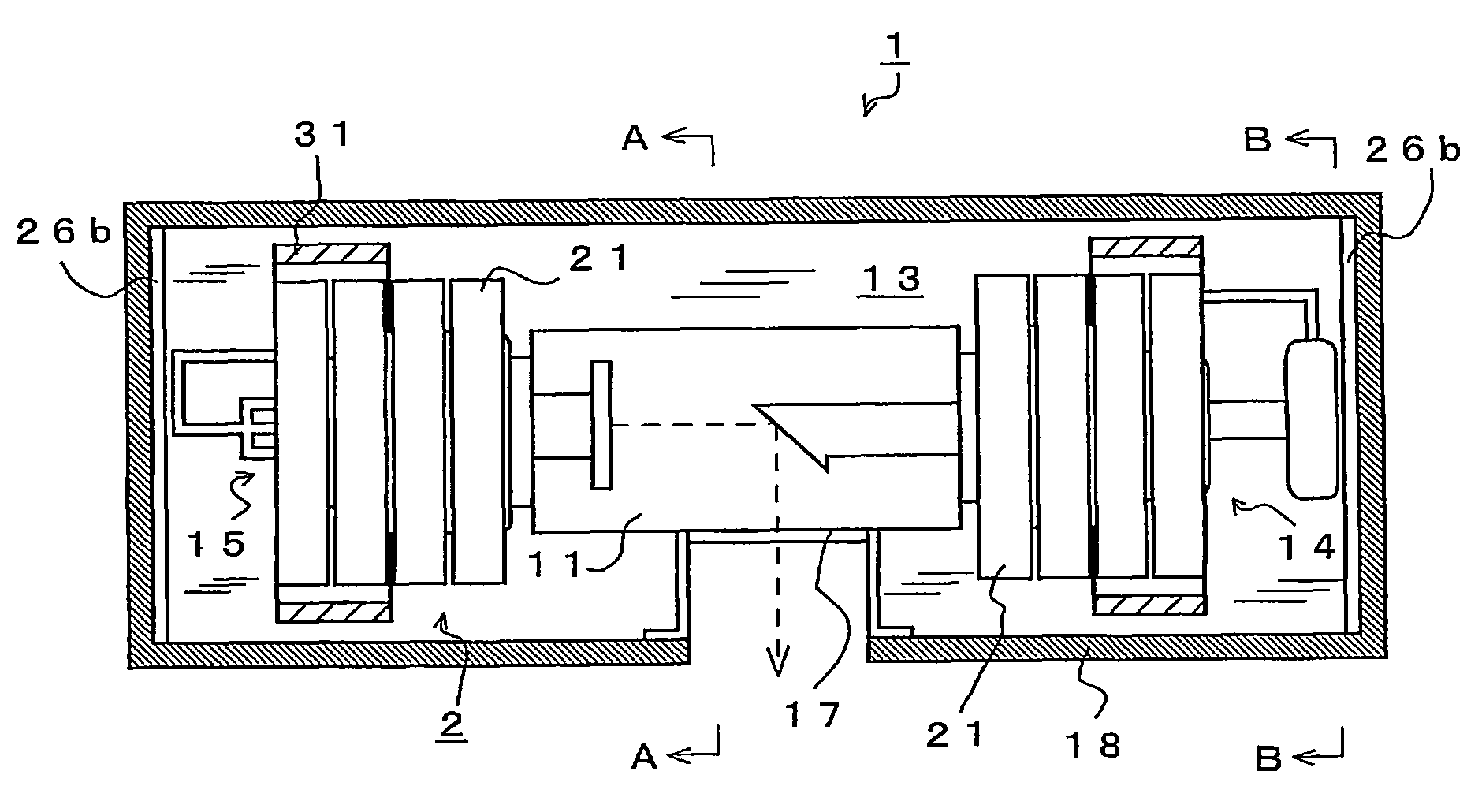
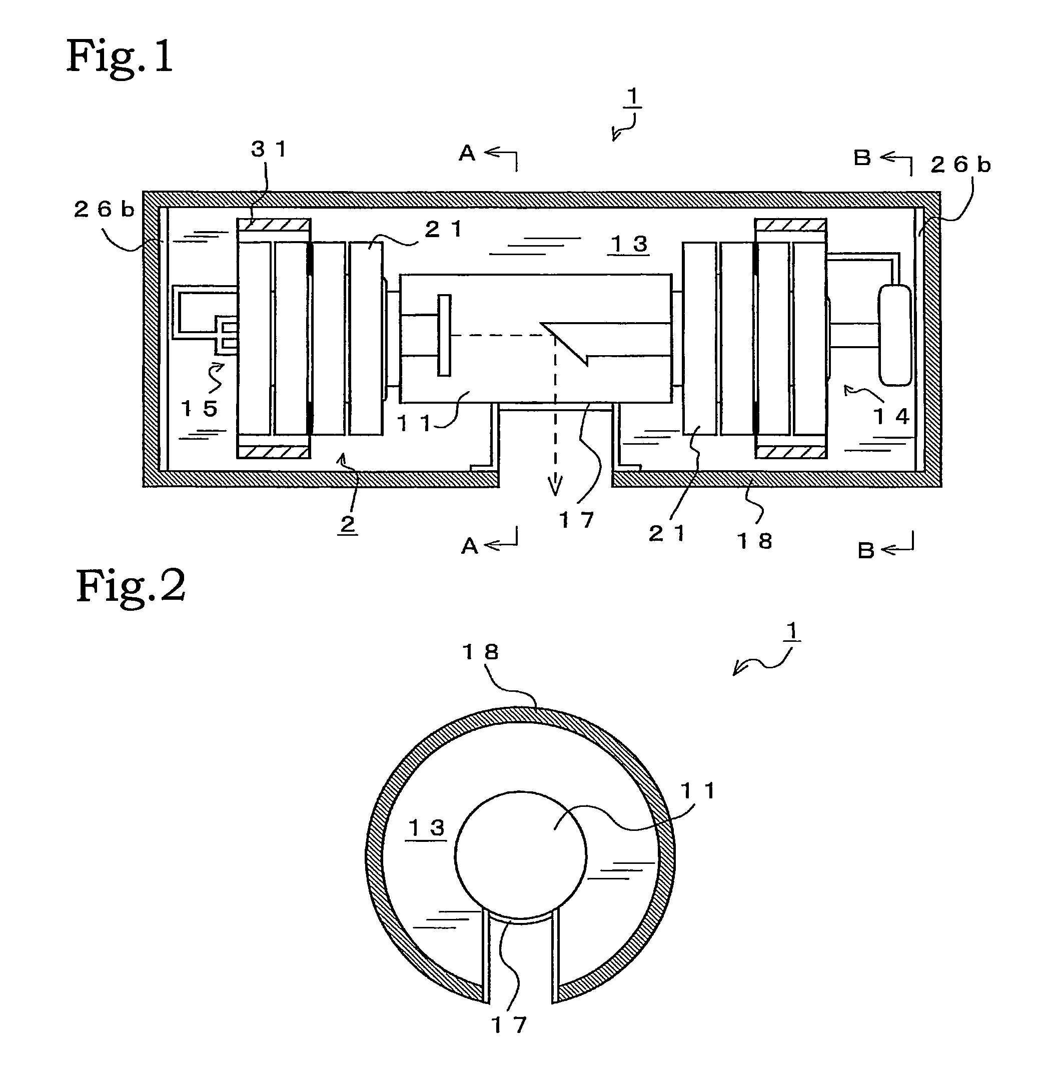
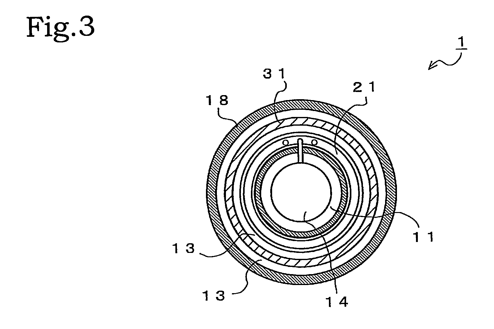
[0036]FIG. 1 shows a schematic of an X-ray irradiator 1. In the X-ray irradiator 1, a cylinder-shaped X-ray tube 11 is installed inside a casing 18, and four voltage amplifying units 21 are installed around each of an X-ray tube anode (hereinafter referred to as an “anode”) 14 and an X-ray tube cathode (hereinafter referred to as a “cathode”) 15. A high-voltage generator 2 including the multiple voltage amplifying units 21 is connected to the anode 14 and the cathode 15, and is also connected to an unillustrated external power supply.

[0037]Auxiliary electric potential plates 31 are installed around the high-voltage generator 2. The auxiliary electric potential plates 31 are capable of reducing the difference in electric potential around the high-voltage generator 2, and accordingly preventing discharge. In addition, an insulation oil 13 or an insulation resin ...


PUM


Abstract

Provided is an X-ray irradiator which reduces the occurrence of discharge resulting from the difference in electric potential in the X-ray irradiator, and which concurrently achieves reduction in size and weight. In an X-ray irradiator (1), an X-ray tube (11) and a high-voltage generator (2) are installed inside a casing (18), and an insulation oil (13) is filled in the casing (18). The high-voltage generator (2) is configured by arranging and electrically connecting together multiple ring-shaped voltage amplifying units (21). An anode (14) and a cathode (15) of the X-ray tube (11) are fitted in and thus installed in hollow portions of the voltage amplifying units (21).

Description

[0001]This is a national stage of PCT / JP09 / 053924 filed Mar. 3, 2009 and published in Japanese, which has a priority of Japanese no. 2008-054078 filed Mar. 4, 2008 and Japanese no. 2009-041025 filed Feb. 24, 2009, hereby incorporated by reference.TECHNICAL FIELD[0002]The present invention relates to an X-ray irradiator, and specifically an X-ray irradiator used for a non-destructive inspection in which specimens such as food and industrial products are irradiated with an X-ray to detect a foreign material and a defect in the specimens on the basis of an amount of X-ray transmission. In addition, the present invention relates to an X-ray irradiator used for an inspection in the field of medicine.BACKGROUND ART[0003]A type of an X-ray irradiator including an X-ray tube, a high-voltage power supply, and a power supply for lighting a filament is most widely used among various types of X-ray irradiators. A high voltage of 10 kV to 500 kV depending on use is applied to the X-ray tube. Onc...

Claims


Application Information

Patent Timeline
Patent Type & Authority Patents(United States)
IPC IPC(8): H05G1/10
CPCH01J35/025H05G1/06H05G1/10
Inventor YAMAMOTO, KEIICHIRO
Owner JOB CORP
Learn More