
Apparatus for securing electronic equipment

a technology for electronic equipment and accessories, applied in the direction of electrical apparatus casings/cabinets/drawers, printed circuit board receptacles, instruments, etc., can solve the problems of difficult removal of components, low electrical communication efficiency, and high vibration of locomotives along the path of travel. achieve the effect of facilitating electrical communication, reducing vibration, and facilitating electrical communication

Active Publication Date: 2012-12-11
GE GLOBAL SOURCING LLC
View PDF68 Cites 11 Cited by
  • Summary
  • Abstract
  • Description
  • Claims
  • Application Information

AI Technical Summary

Benefits of technology

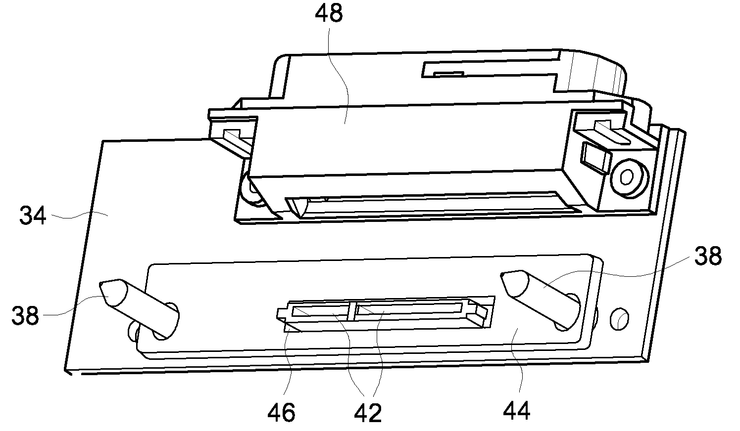
The present invention provides an apparatus for securing electronic equipment, such as a mass data storage device or an SSD, in a high-vibration environment. The apparatus includes a shell for removable securement of the electronic device, a dock for electrical communication with the device, and a damping mechanism to reduce vibrations and movement between the device and the dock. The apparatus also includes guides and locator pins to ensure proper mating alignment between the device and the dock, and a gasket to further reduce vibrations and movement. The technical effects of the invention include improved protection and reliability of electronic equipment in high-vibration environments, facilitation of proper mating alignment, and reduction of vibratory forces and movement between the device and the dock.

Problems solved by technology

In particular, locomotives may present a high-vibration environment due to track irregularities and the like.
Moreover, locomotives may encounter relatively extreme temperatures along their path of travel.
Additionally, the on-board electronics often include components that are not easily removed.
Removal, however, often requires the use of tools and is relatively labor and time intensive.

Method used


Image

  • Apparatus for securing electronic equipment
  • Apparatus for securing electronic equipment
  • Apparatus for securing electronic equipment

Examples


Embodiment Construction

[0028]Reference will be made below in detail to exemplary embodiments of the invention, examples of which are illustrated in the accompanying drawings. Wherever possible, the same reference numerals used throughout the drawings refer to the same or like parts.

[0029]As described in detail below, an embodiment of the present invention provides an apparatus for securing electronic equipment in a high vibration environment that is easy to use, robust, and tamper resistant. Embodiments of the inventive apparatus include beneficial damping, alignment, and heating features, as well as secure mating connectors.

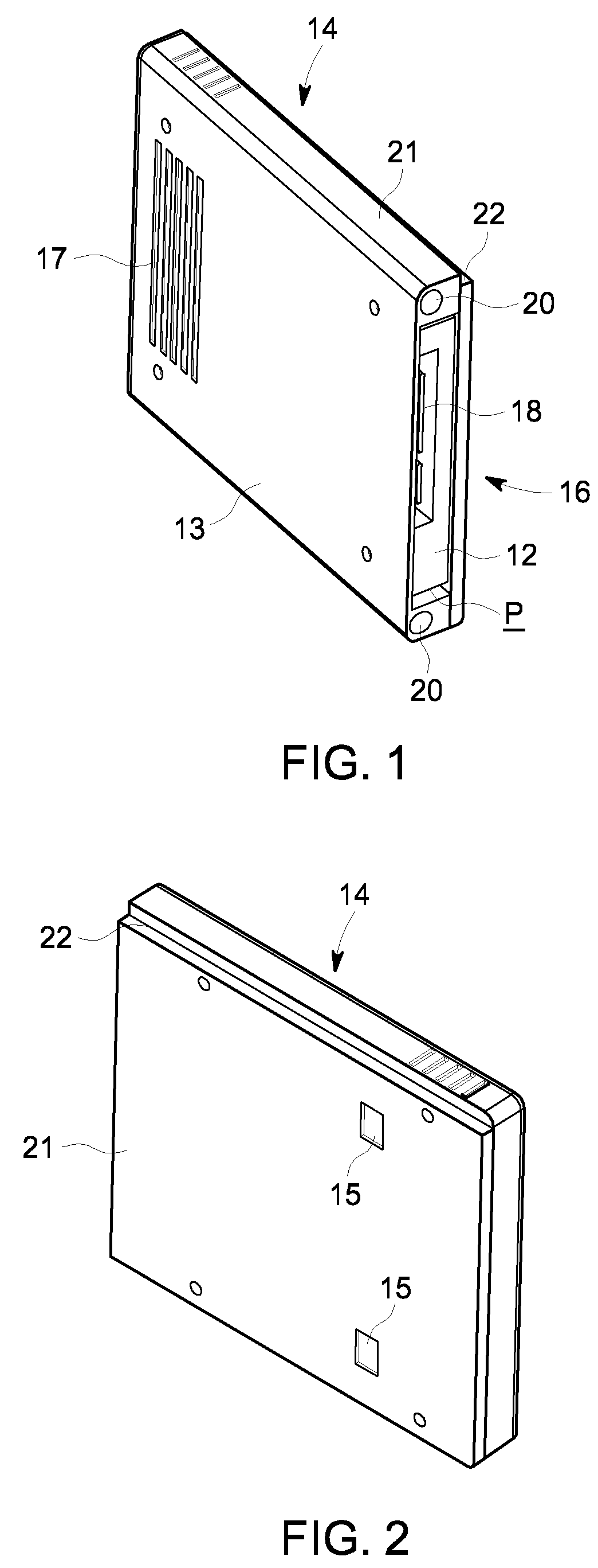
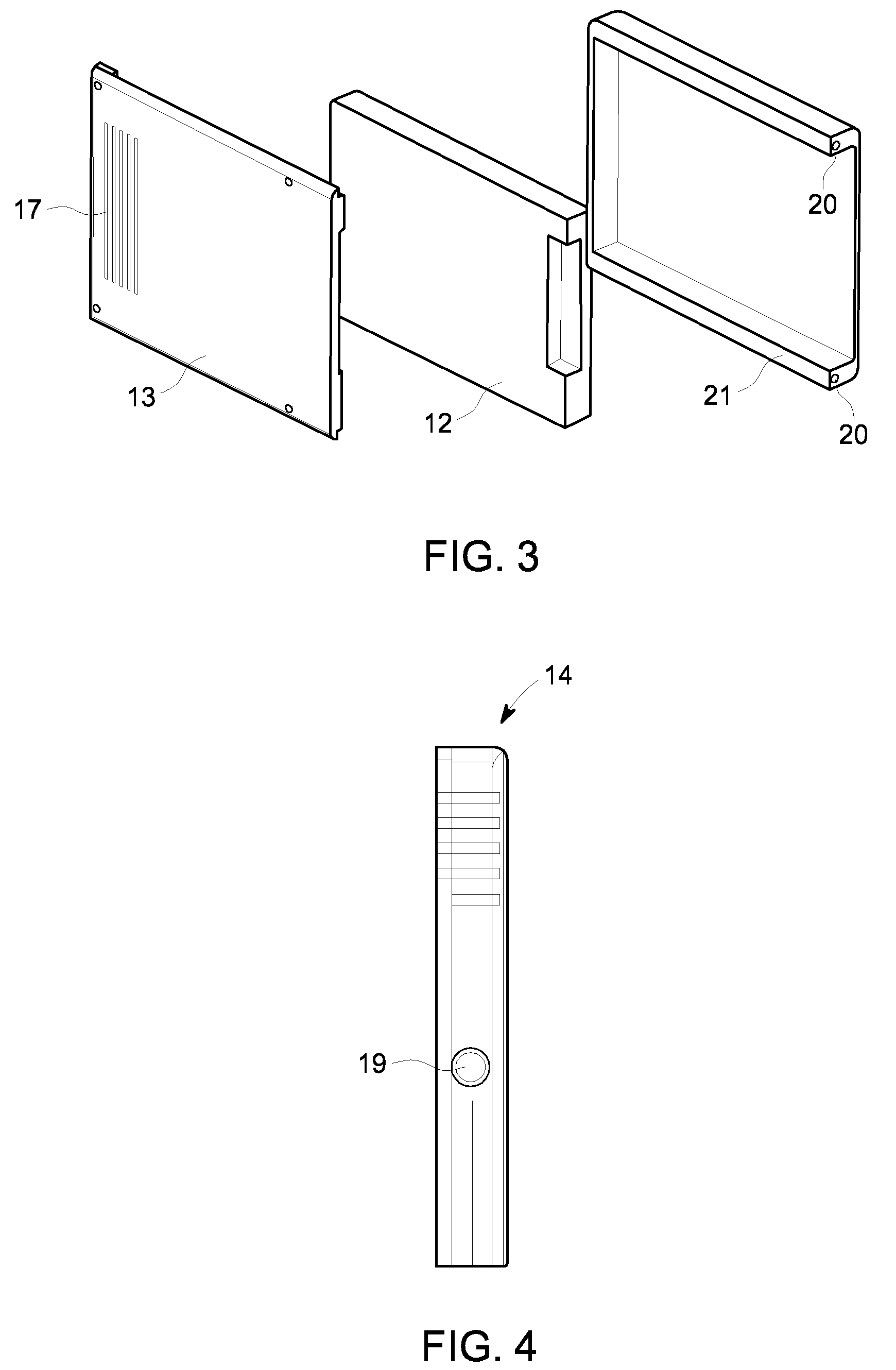
[0030]Referring generally to FIGS. 1-17, an embodiment includes a shell 14 that contains the electronic device to be secured. The shell 14 is removably fixed within a dock 30. A hinged external housing 60 is fastened to the dock 30 to isolate and further protect both the shell 14 and dock 30.

[0031]More specifically, and as shown in FIGS. 1 and 2, the shell 14 contains the electronic e...


PUM


Abstract

An apparatus for securing electronic equipment. The apparatus includes an electronic device having a first mating portion. The device is removably secured within a shell, which has an open end allowing access to the first mating portion. The apparatus further includes a dock having a second mating portion and an output connector in electrical communication with the second mating portion. The dock removably receives the shell to facilitate electrical communication between the first and second mating portions. The output connector facilitates electrical communication between the electronic device and a device external to the dock. The apparatus also includes a damping mechanism to reduce vibratory forces on the first and second mating portions and relative movement between the portions.

Description

FIELD OF THE INVENTION[0001]Embodiments of the invention relate generally to an apparatus for securing electronic equipment and, in particular, to a system for securing an electronic device, such as a solid state drive, in a high-vibration environment.BACKGROUND OF THE INVENTION[0002]Modern locomotives typically include on-board electronics to monitor and control their various systems, such as, for example, their traction, engine, and braking systems. The electronics often include one or more processors coupled to a mass data storage system via a bus interface. These interconnected components are all stored within the locomotive, which raises several potential considerations.[0003]In particular, locomotives may present a high-vibration environment due to track irregularities and the like. Moreover, locomotives may encounter relatively extreme temperatures along their path of travel. As will be appreciated, on-board electronics are exposed to these conditions.[0004]Additionally, the ...

Claims


Application Information

Patent Timeline
Patent Type & Authority Patents(United States)
IPC IPC(8): G06F1/16H05K5/00H05K7/00
CPCH05K7/1427
Inventor CHUNG, WING YEUNGCAFFERTY, GERARD MICHAEL
Owner GE GLOBAL SOURCING LLC
Learn More