Image display apparatus, correction circuit thereof and method for driving image display apparatus
a technology of image display and correction circuit, which is applied in the direction of instruments, computing, electric digital data processing, etc., can solve the problems of deteriorating the quality of the image displayed, and achieve the effect of reducing image quality deterioration and higher accuracy
- Summary
- Abstract
- Description
- Claims
- Application Information
AI Technical Summary
Benefits of technology
Problems solved by technology
Method used
Image
Examples
first embodiment
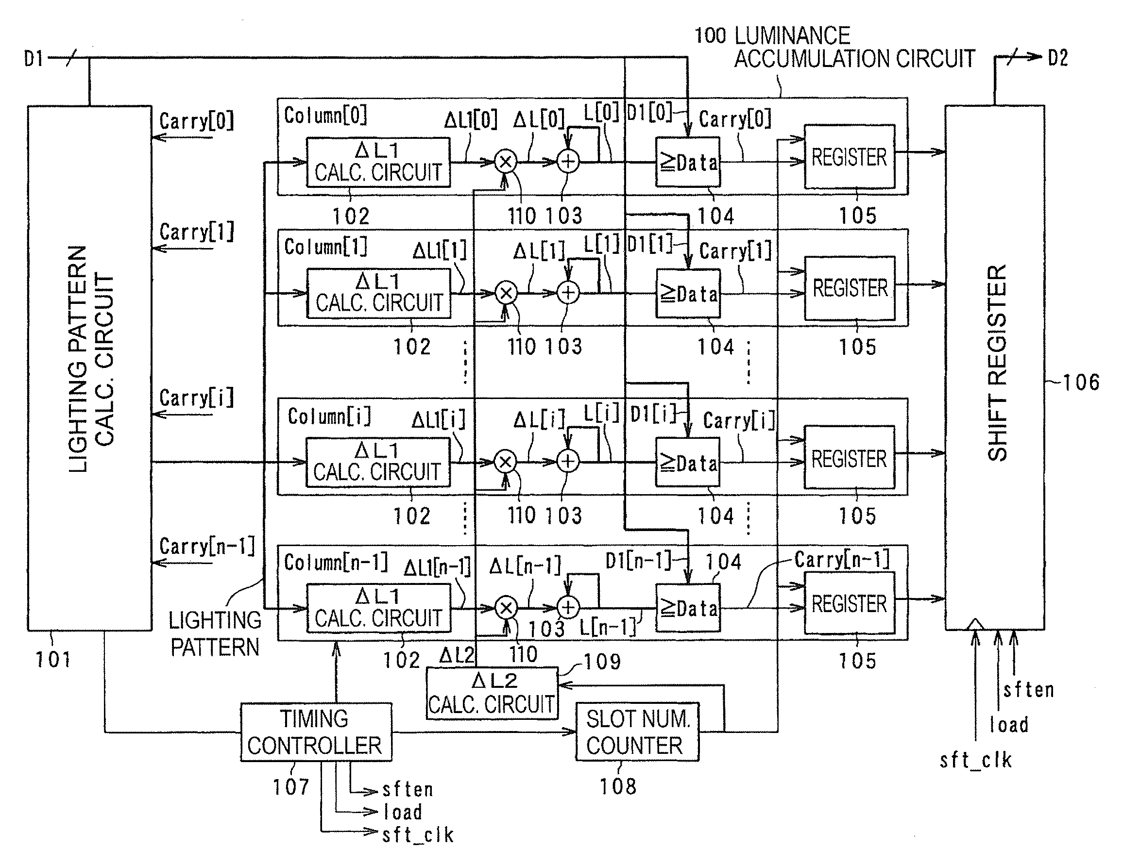
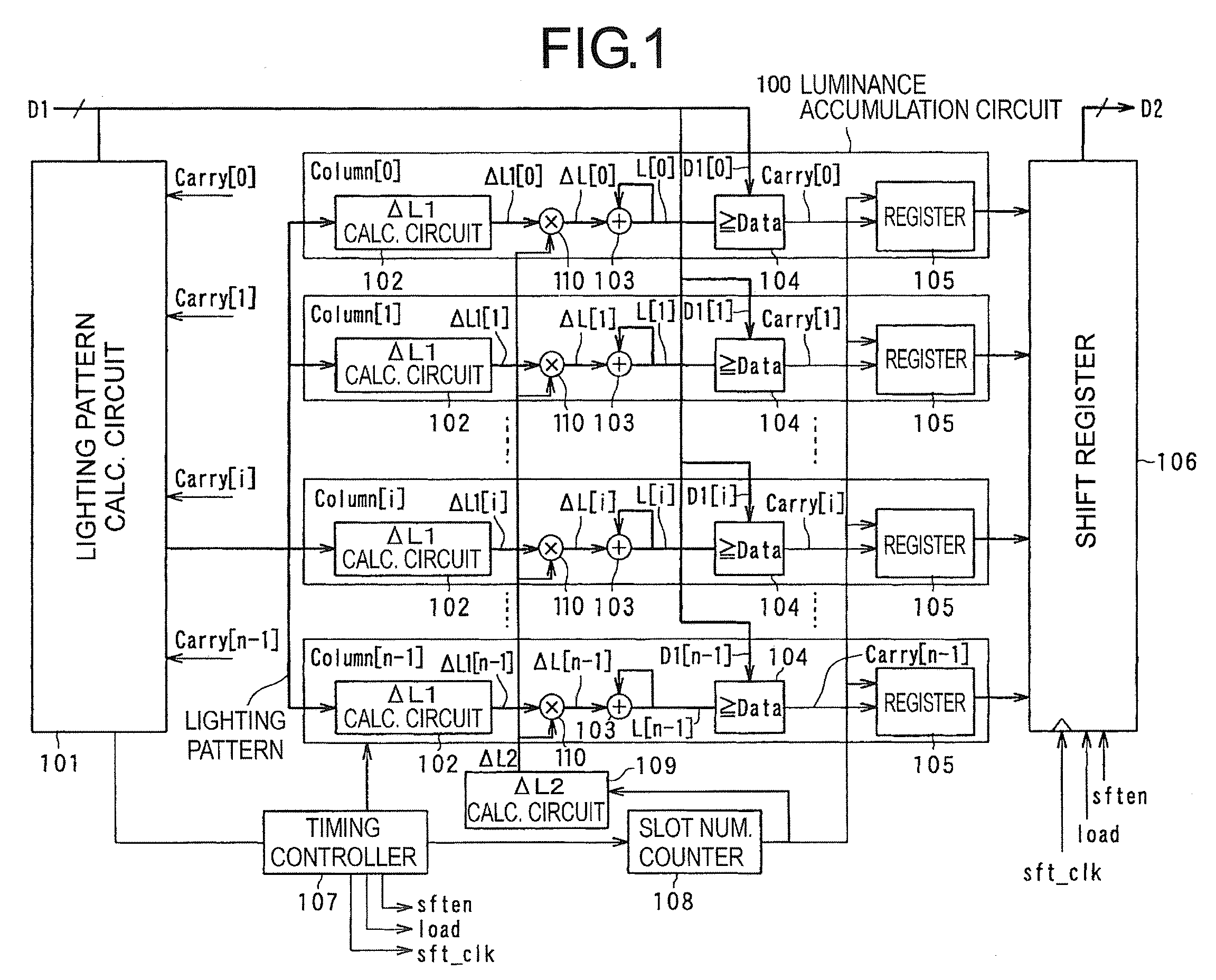
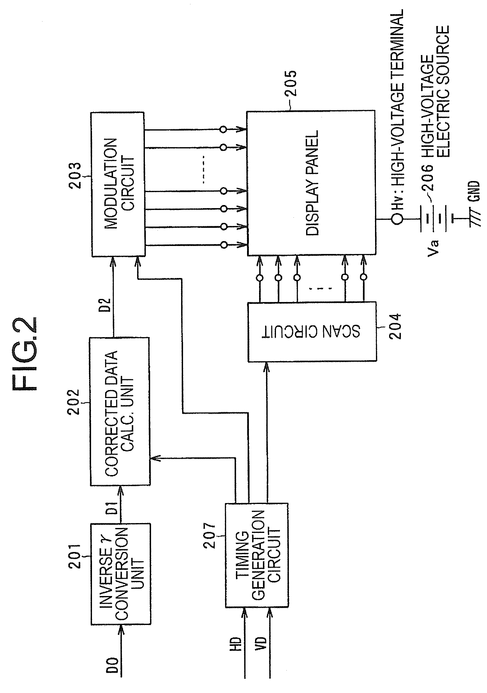
[0050]The image display apparatus according to the first embodiment generally includes a display panel with plural surface conduction electron-emitting devices arranged in simple matrix, a driving circuit (scan circuit, modulation circuit) for driving the display panel, and a correction circuit. According to this embodiment, the driving circuit drives the row wirings (scan wirings) in line sequence and applies the modulation pulse in which at least a pulse width is modulated to the column wirings (modulation wirings). The lighting time of each device is controlled by the pulse width. In addition to the lighting time control by the pulse width modulation (PWM), the lighting strength within a lighting period is desirably controlled by the pulse height modulation (PHM). In the description that follows, however, only the pulse width modulation is shown as an example to facilitate the understanding.
[0051]In the image display apparatus according to this embodiment, the input image data is...
second embodiment
[0129]In the first embodiment, as shown in FIG. 1, the luminance accumulation circuit is arranged for each column wiring. According to the second embodiment, in contrast, plural column wirings are divided into plural blocks, and the luminance accumulation circuit is arranged for each block. By executing the process block by block, the corrected data can be calculated quickly while at the same time making it possible to reduce the circuit size advantageously.
[0130]FIG. 7 is a diagram showing the configuration of the image display apparatus according to the second embodiment. The difference from the first embodiment lies in that the corrected data calculation unit 202 is replaced by a discrete corrected data calculation unit 703 and a biaxial interpolation circuit 704. In this embodiment, the discrete corrected data calculation unit 703 and the biaxial interpolation circuit 704 make up a correction circuit. The other parts of the configuration are similar to the corresponding parts of...
PUM
 Abstract
Description
Claims
Application Information
 - R&D
- Intellectual Property
- Life Sciences
- Materials
- Tech Scout
- Unparalleled Data Quality
- Higher Quality Content
- 60% Fewer Hallucinations
Browse by: Latest US Patents, China's latest patents, Technical Efficacy Thesaurus, Application Domain, Technology Topic, Popular Technical Reports.
© 2025 PatSnap. All rights reserved.Legal|Privacy policy|Modern Slavery Act Transparency Statement|Sitemap|About US| Contact US: help@patsnap.com


