
Fluid ejecting apparatus, fluid ejecting head control method in fluid ejecting apparatus, and driving waveform generating apparatus for fluid ejecting head

a technology of fluid ejecting apparatus and control method, which is applied in the direction of printing, other printing apparatus, etc., can solve the problems of increasing the number of wires, increasing the number of signal lines, and complication of wiring structure and assembly work, so as to reduce the time for occupying storage area and reduce the number of wirings

Active Publication Date: 2012-12-11
SEIKO EPSON CORP
View PDF6 Cites 2 Cited by
  • Summary
  • Abstract
  • Description
  • Claims
  • Application Information

AI Technical Summary

Benefits of technology

The invention provides a fluid ejecting apparatus with a driving waveform generating apparatus that can indicate the generation timing of a driving waveform without transmitting a timing signal through a timing signal line. This reduces the number of required wirings and the associated costs. The apparatus includes a waveform designation signal transmitter that transmits a waveform designation signal and information regarding the ejection of fluid from the fluid ejecting head through a single wiring. The waveform generator transmits the driving waveform at a timing after a predetermined time elapses from the reception start or completion of the waveform designation signal. This synchronizes the driving waveform with the reception timing of the waveform designation signal, and reduces the waiting time for transmitting the driving waveform. The invention also provides a method for reducing the number of signal lines needed for transmitting the waveform designation signal.

Problems solved by technology

However, since M signal lines are necessary, an increase in the number of wires is inevitable.
However, even in such a configuration case, timing signal lines for transmitting M timing signals are required between the upper level substrate and the plurality of (M) lower level substrates, resulting in complication of a wiring structure and assembly work due to an increase in the number of the signal lines.

Method used


Image

  • Fluid ejecting apparatus, fluid ejecting head control method in fluid ejecting apparatus, and driving waveform generating apparatus for fluid ejecting head
  • Fluid ejecting apparatus, fluid ejecting head control method in fluid ejecting apparatus, and driving waveform generating apparatus for fluid ejecting head
  • Fluid ejecting apparatus, fluid ejecting head control method in fluid ejecting apparatus, and driving waveform generating apparatus for fluid ejecting head

Examples


Embodiment Construction

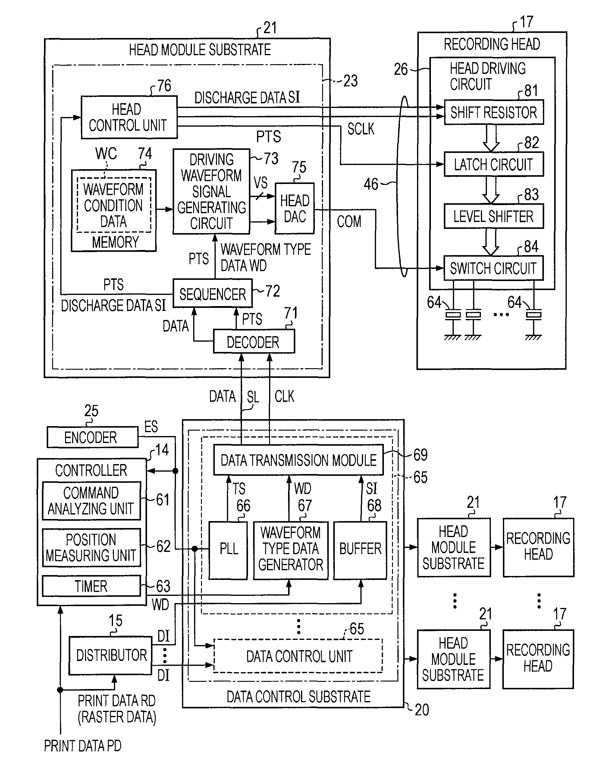
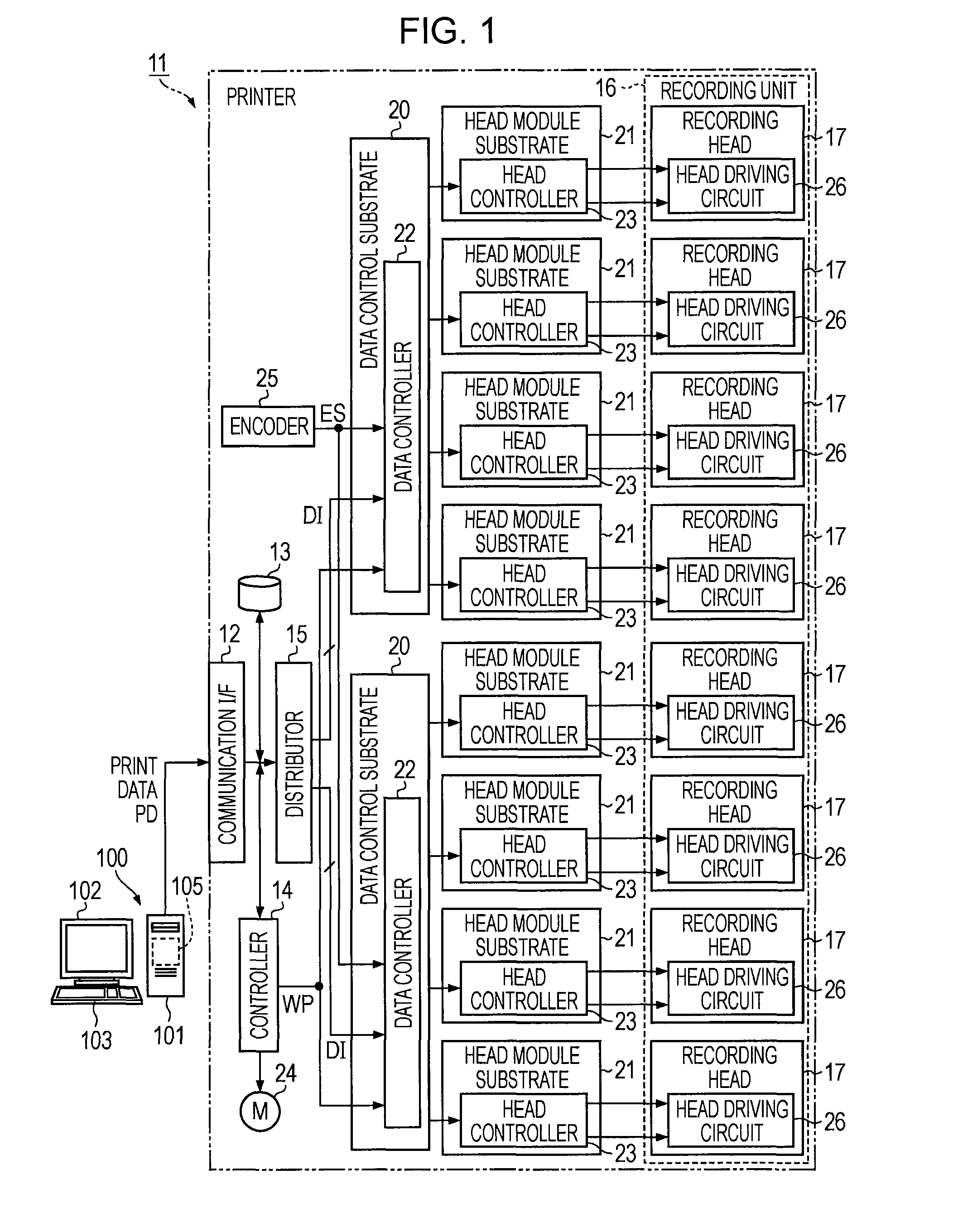
[0032]Hereinafter, one embodiment of the invention will be described with reference to FIGS. 1 to 7. FIG. 1 is a block diagram illustrating the electrical configuration of an ink jet printer as a fluid ejecting apparatus.

[0033]As shown in FIG. 1, the ink jet printer (hereinafter, simply referred to as a “printer 11”) is communicatively connected to a host apparatus 100 to perform printing based on printing data PD received from the host apparatus 100. The host apparatus 100, for example, includes a personal computer, and is provided with a body 101, a monitor 102 and an input device 103. The body 101 has a printer driver 105 therein. For example, if a user commands performance of printing by operating the input device 103, the printer driver 105 generates printing data PD interpretable by the printer 11 from data (image data or document data) such as an image and a document displayed on the monitor 102, and transmits the printing data PD to the printer 11.

[0034]In detail, the printe...


PUM


Abstract

Disclosed is a fluid ejecting apparatus including a fluid ejecting head that ejects fluid, a waveform generator that transmits a driving waveform for driving the fluid ejecting head to the fluid ejecting head, and a waveform designation signal transmitter that transmits a waveform designation signal for designating a driving waveform to be generated to the waveform generator, wherein the waveform generator transmits the driving waveform at a timing based on a reception timing of the waveform designation signal.

Description

BACKGROUND[0001]1. Technical Field[0002]The present invention, for example, relates to a fluid ejecting apparatus provided with a fluid ejecting head that ejects fluid such as ink as with an ink jet printer and the like, a fluid ejecting head control method in the fluid ejecting apparatus, and a driving waveform generating apparatus for a fluid ejecting head.[0003]2. Related Art[0004]According to the related art, as one of a fluid ejecting apparatus that ejects fluid, an ink jet printer provided with a recording head that ejects ink has been known (e.g., JP-A-2003-1824 and the like). In the printer disclosed in JP-A-2003-1824, a voltage with a predetermined driving waveform is applied to a piezoelectric vibrator provided for each nozzle in the recording head, resulting in ejection of an ink droplet. A driving waveform signal (a trapezoidal waveform signal) for controlling the waveform of the voltage applied to the piezoelectric vibrator is generated by a driving signal generating ci...

Claims


Application Information

Patent Timeline
Patent Type & Authority Patents(United States)
IPC IPC(8): B41J29/38
CPCB41J2/04541B41J2/04573B41J2/04581B41J2/04588
Inventor KURASHINA, TERUKI
Owner SEIKO EPSON CORP
Learn More