
Animal breast pump device

Inactive Publication Date: 2012-12-04
SIMINAK KATHERINE L +1
View PDF15 Cites 0 Cited by
  • Summary
  • Abstract
  • Description
  • Claims
  • Application Information

AI Technical Summary

Benefits of technology

[0014]A further object of the animal breast pump device is to provide ideals angles of fit and operat

Problems solved by technology

Breast pumps are well known for use with humans

Method used


Image

  • Animal breast pump device
  • Animal breast pump device
  • Animal breast pump device

Examples


Example

DETAILED DESCRIPTION OF THE DRAWINGS

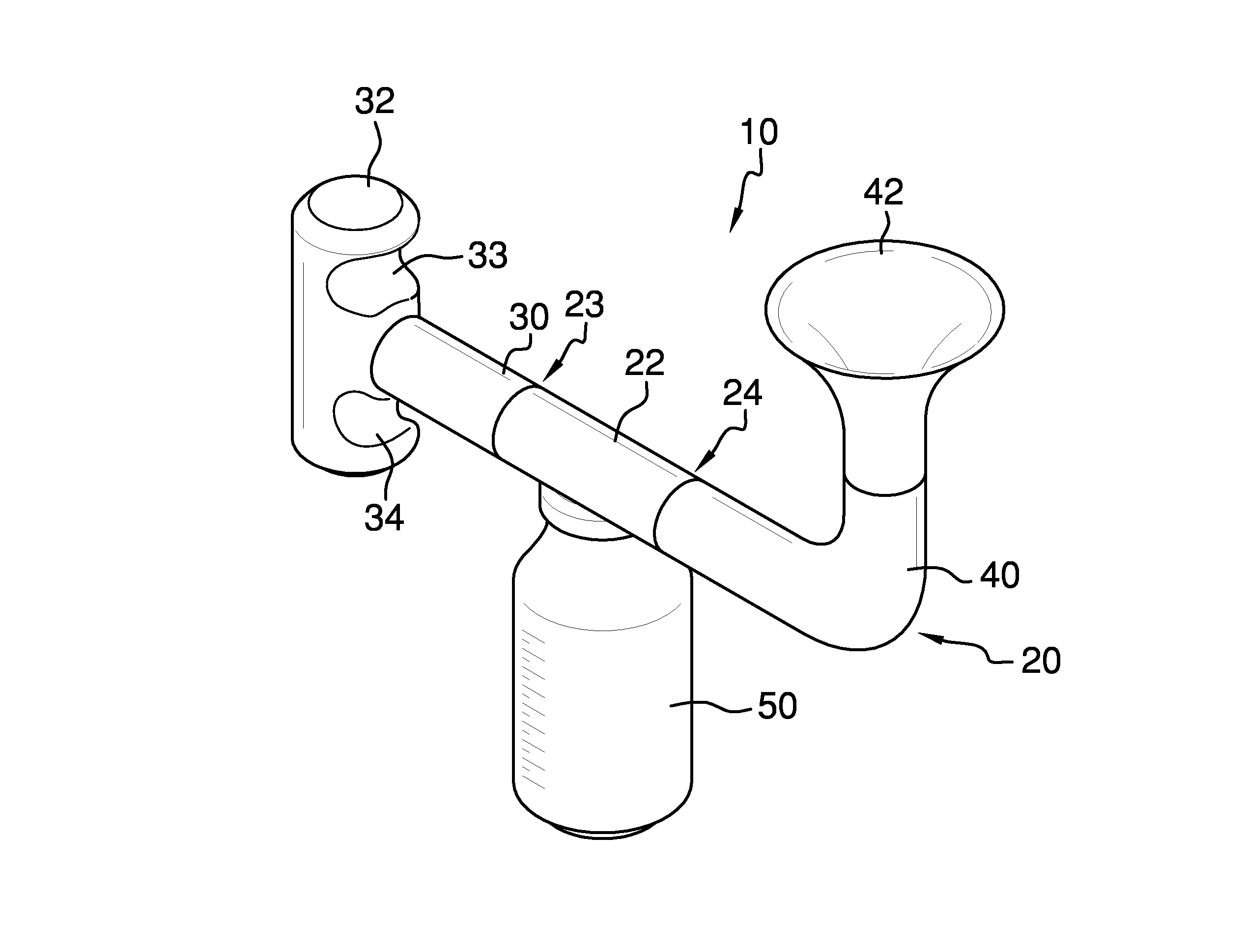
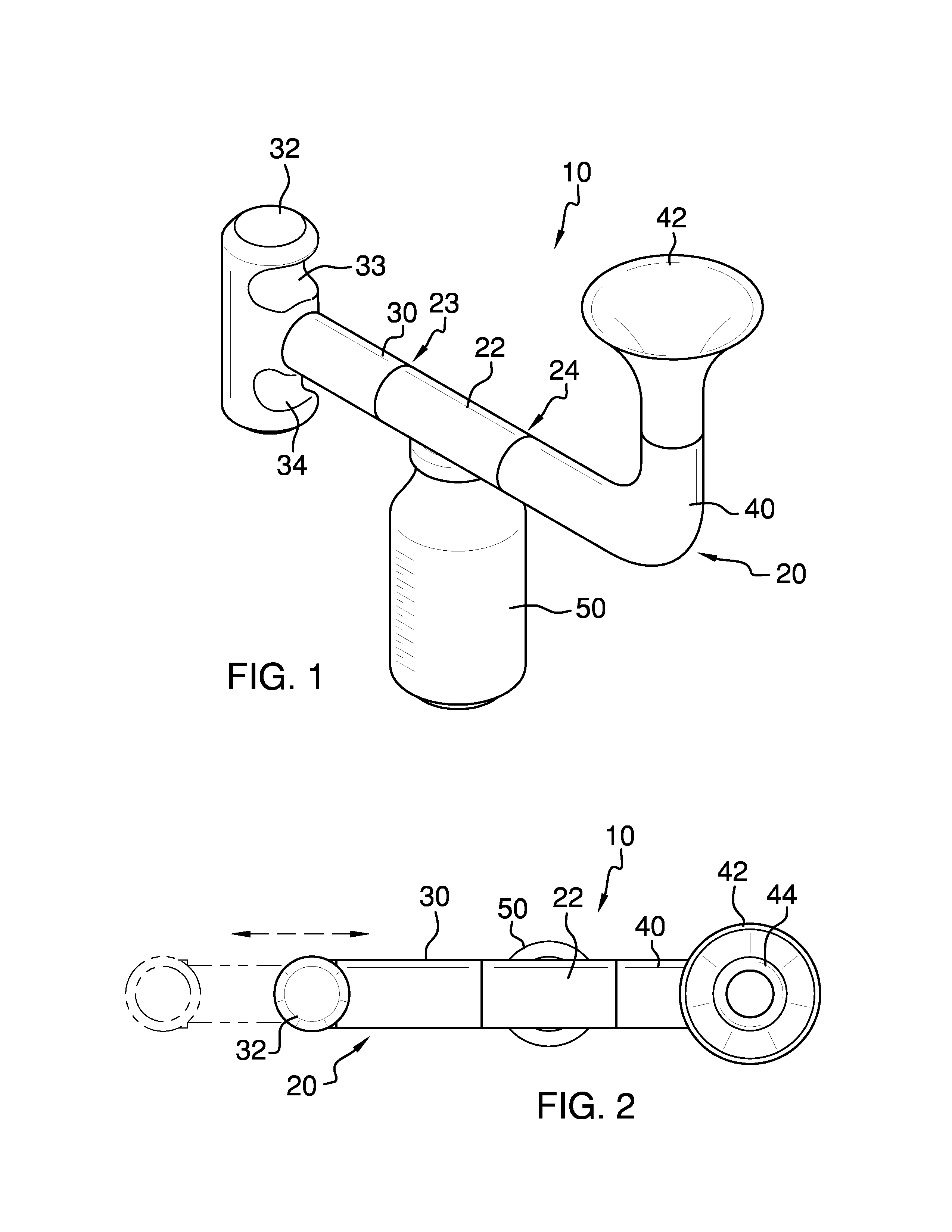
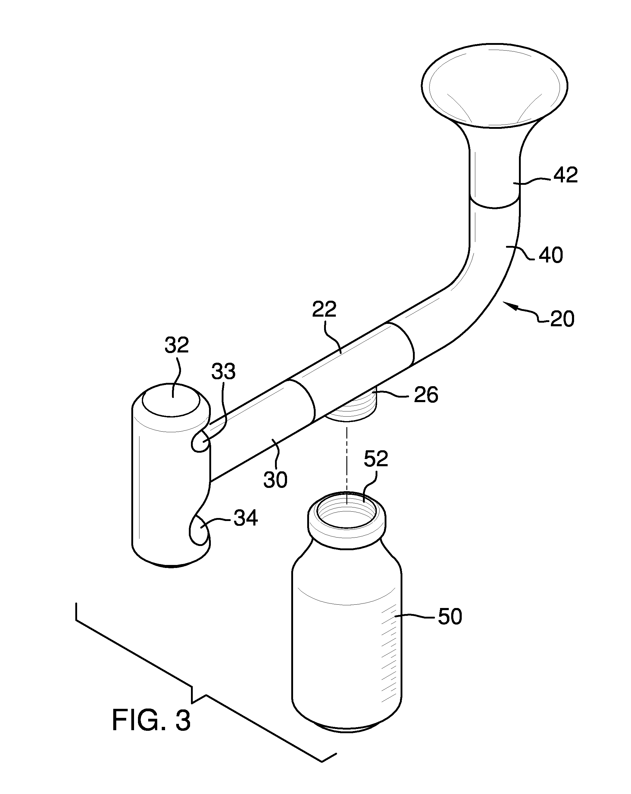
[0025]With reference now to the drawings, and in particular FIGS. 1 through 6 thereof, the principles and concepts of the animal breast pump device generally designated by the reference number 10 will be described.

[0026]Referring to FIG. 4, the device 10 partially comprises the extraction mechanism 20. The extraction mechanism 20 comprises a cylindrical horizontal T section 22 having a first end 23 spaced apart from a second end 24. The male thread 25 is disposed on the second end 24. The bottom male thread 26 is disposed downwardly on the T section 22. The cylindrical plunger pump 30 is disposed on T section 22 first end 23.

[0027]Referring to FIG. 1, the cylindrical T-handle 32 is disposed outwardly and perpendicularly on the cylindrical plunger pump 30. An upper finger groove 33 is disposed medially on the cylindrical T-handle 32. The upper finger groove 33 is disposed above the cylindrical plunger pump 30. The lower finger groove 34 is disposed...


PUM


Abstract

The animal breast pump device provides an extraction mechanism having a cylindrical horizontal T section having a first end spaced apart from a second end with a bottom male thread disposed downwardly on the T section, a cylindrical plunger pump disposed on T section first end, a cylindrical union removably disposed on the T section male thread, a suction funnel removably and threadably disposed on the union, a flexible retainer disposed centrally within the suction funnel, and a bottle having an upwardly disposed female thread, the female thread removably fitted to the T section bottom male thread.

Description

CROSS-REFERENCE TO RELATED APPLICATIONS[0001]Not ApplicableFEDERALLY SPONSORED RESEARCH OR DEVELOPMENT[0002]Not ApplicableINCORPORATION BY REFERENCE OF MATERIAL SUBMITTED ON A COMPACT DISK[0003]Not Applicable[0004]Be it known that we, Katherine L. Siminak and Jinae K. Siminak, both citizens of the United States, have invented new and useful improvements in an animal breast pump device as described in this specification.BACKGROUND OF THE INVENTION[0005]Breast pumps are well known for use with humans, with fewer devices being suited to animal use. Dogs provide an excellent example wherein a breast pump can be a particularly useful device. Zoo animals provide further example. The present device is ideal for use on a variety of animals.FIELD OF THE INVENTION[0006]The animal breast pump device relates to breast pumps and more especially to a breast pump particularly suited to animal use.SUMMARY OF THE INVENTION[0007]The general purpose of the animal breast pump device, described subseque...

Claims


Application Information

Patent Timeline
IPC IPC(8): A61M1/06
CPCA61M1/06A61M2250/00A01J5/06A01J5/047A01J9/08
Inventor SIMINAK, KATHERINE L.SIMINAK, JINAE K.
Owner SIMINAK KATHERINE L
Learn More