Eureka AIR delivers breakthrough ideas for toughest innovation challenges, trusted by R&D personnel around the world.

Diagnostic method for a ball bearing, in particular for an angular-contact ball bearing, a corresponding diagnostic system, and use of the diagnostic system

a technology of ball bearings and diagnostic methods, applied in the direction of instruments, nuclear elements, machines/engines, etc., can solve the problems of inability to assign vibration data clearly to the respective affected machine components, inability to achieve automatic analysis of angular-contact ball bearings, and inability to achieve high reliability. , to achieve the effect of increasing mechanical load and increasing reliability of diagnostic methods

Active Publication Date: 2012-11-20
WEISS SPINDELTECHNOLOGIE GMBH
View PDF16 Cites 3 Cited by
  • Summary
  • Abstract
  • Description
  • Claims
  • Application Information

AI Technical Summary

Benefits of technology

[0025]According to another advantageous feature of the present invention, the bearing frequency may be determined at a maximum amplitude at its respective position in the measurement frequency spectrum. The reliability of the diagnostic method is thereby increased. It is preferred to continue to measure the amplitude in the case of the respective bearing frequencies, and to “search for” the respective amplitude maximum in the frequency range around the expected, respective fundamental kinematic frequency.
[0026]According to another advantageous feature of the present invention, a second diagnostic message can be outputted when a maximum amplitude of at least one of the currently determined bearing frequencies exceeds a predefined limit amplitude. Moreover, by evaluating the height of the frequency amplitudes, i.e. the amplitude, it is possible to come to a conclusion on the mechanical loading of the ball bearing, increasing amplitude values indicating an increasing mechanical load.

Problems solved by technology

However, this has so far not been possible with a sufficiently high reliability, since there are no generally valid, informative limit values relating to the probability of failure of rapidly rotating angular-contact ball bearings.
However, these limit values can be transferred only conditionally to similar machine tools and similar processes.
Because of the high outlay on metrology and of the high costs associated therewith, no automated analysis of angular-contact ball bearings is currently undertaken.
However, it is mostly impossible here to assign the vibration data clearly to the respective affected machine component or to a present cause.
However, spectra cannot be used for early detection of rolling bearing defects, because the extremely low energy defect components or frequency components are mostly covered by high energy machine vibrations.
Stochastic signal components are suppressed, with the result that even small defects can be displayed independently of the machine vibrations, which are substantially higher in energy.
This method has a comparatively good signal-to-noise ratio, and it is, in addition, relatively insensitive to rotational speed fluctuations.
Disadvantageously, these measurements and the required outlay on parameterization for a respective angular-contact ball bearing and for the affected machine are complex.

Method used


Image

  • Diagnostic method for a ball bearing, in particular for an angular-contact ball bearing, a corresponding diagnostic system, and use of the diagnostic system
  • Diagnostic method for a ball bearing, in particular for an angular-contact ball bearing, a corresponding diagnostic system, and use of the diagnostic system
  • Diagnostic method for a ball bearing, in particular for an angular-contact ball bearing, a corresponding diagnostic system, and use of the diagnostic system

Examples


Embodiment Construction

[0040]Throughout all the figures, same or corresponding elements may generally be indicated by same reference numerals. These depicted embodiments are to be understood as illustrative of the invention and not as limiting in any way. It should also be understood that the figures are not necessarily to scale and that the embodiments are sometimes illustrated by graphic symbols, phantom lines, diagrammatic representations and fragmentary views. In certain instances, details which are not necessary for an understanding of the present invention or which render other details difficult to perceive may have been omitted.

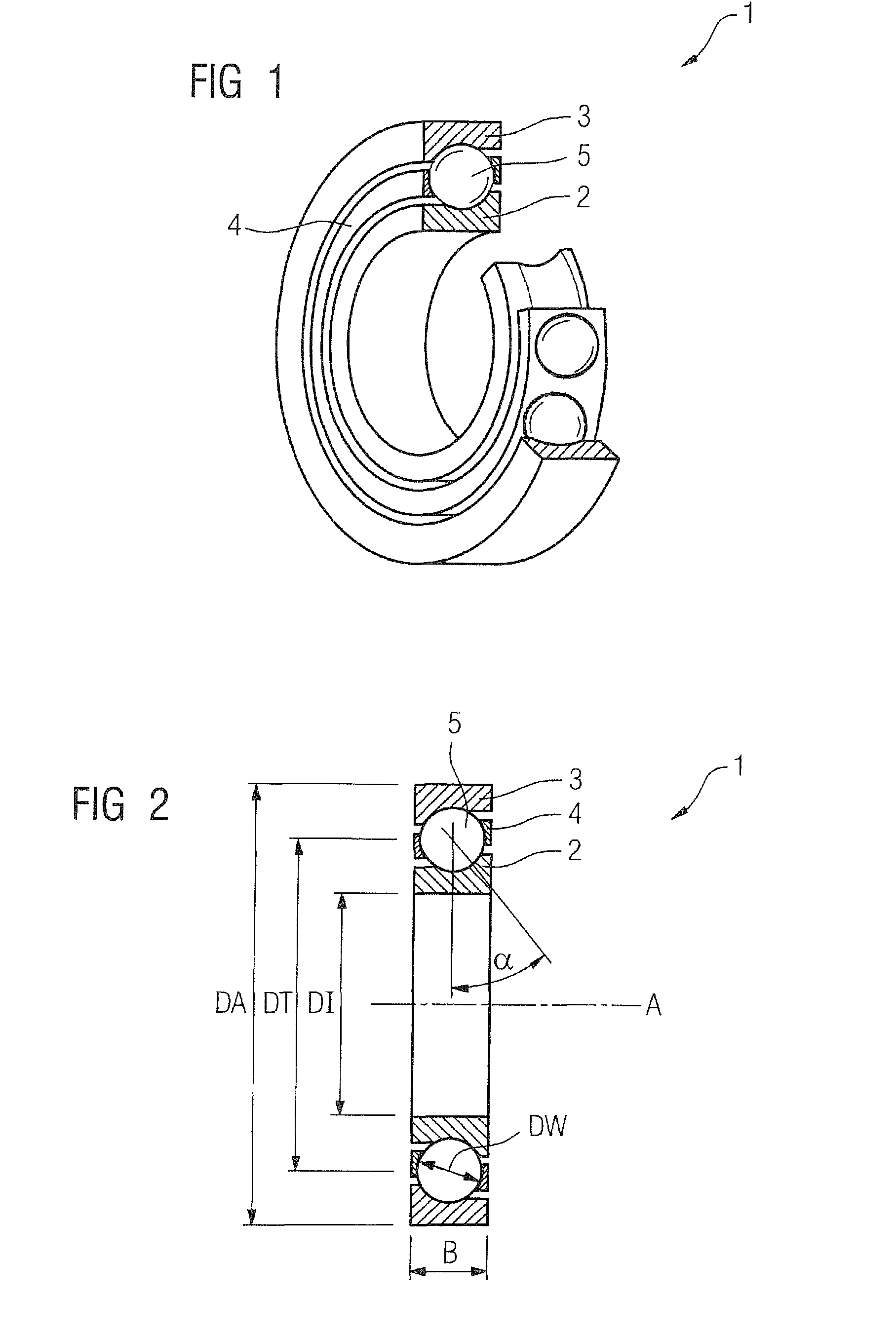
[0041]Turning now to the drawing, and in particular to FIG. 1, there is shown a perspective view of an angular-contact ball bearing 1 as an example of a ball bearing. It has a bearing inner race, denoted by the reference 2, a bearing outer race 3 and a multiplicity of bearing balls 5 in a bearing cage 4 that are arranged between the two bearing races 2, 3.

[0042]FIG. 2 shows ...


PUM

PropertyMeasurementUnit
pressure angleaaaaaaaaaa

Abstract

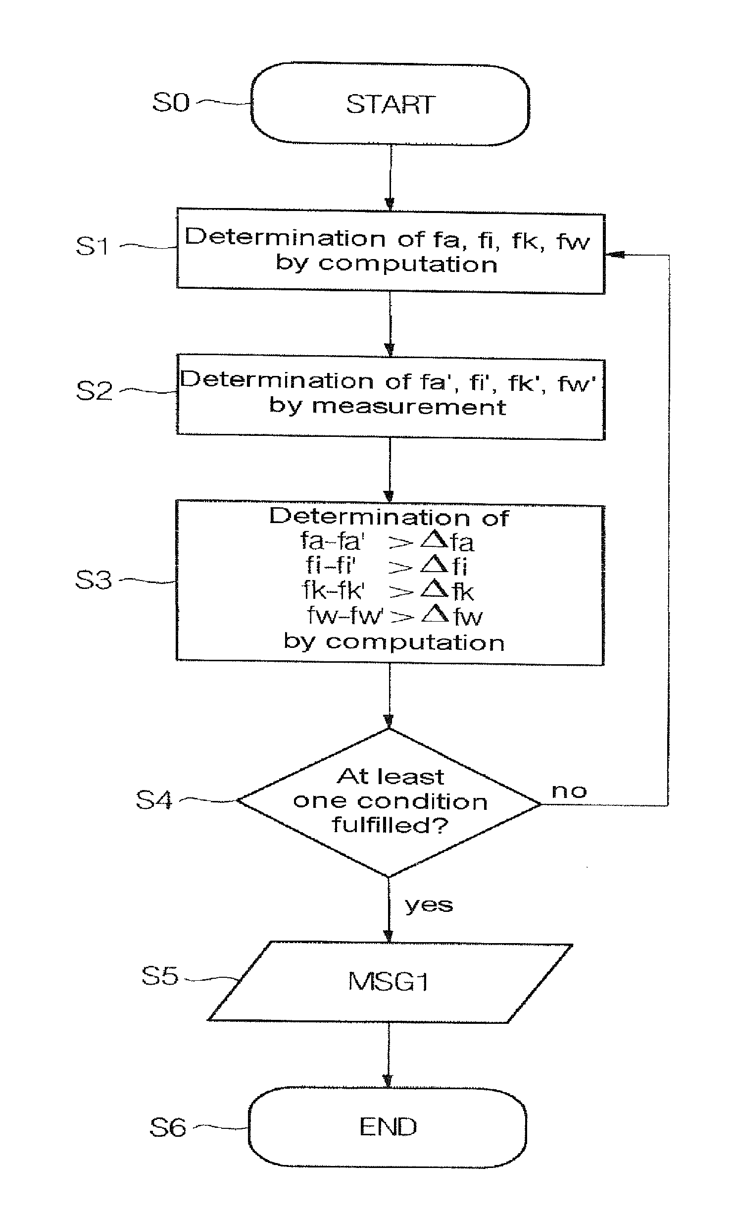
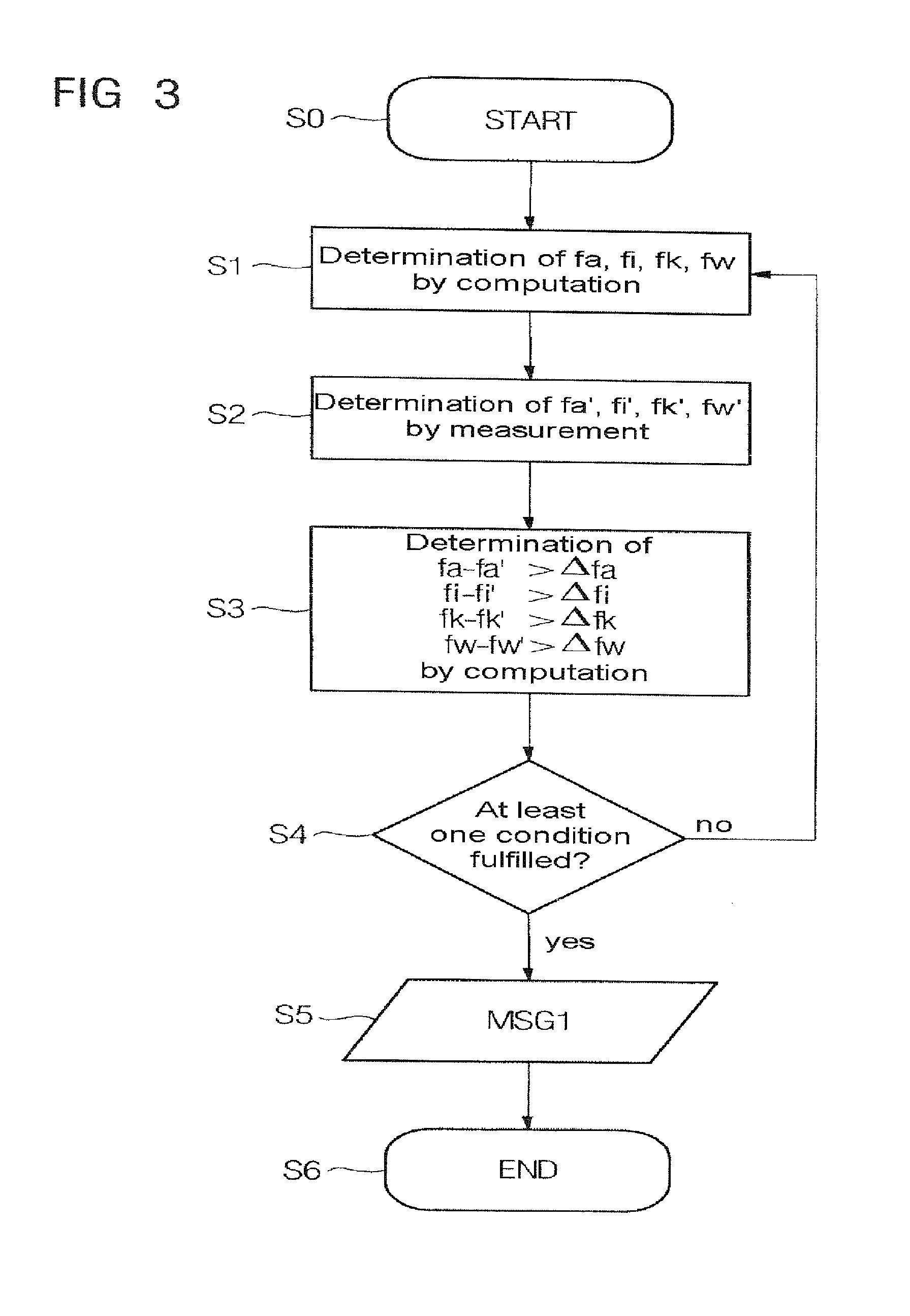
In a diagnostic method for at least one ball bearing, in particular for an angular-contact ball bearing for bearing a rapidly rotating spindle, mechanical vibration caused by the respective angular-contact ball bearing is acquired by at least one vibration sensor and outputted as a corresponding vibration signal. At least one bearing characteristic, fundamental kinematic frequency dependent on a current bearing rotational frequency is determined by computation. A corresponding bearing frequency in a measurement frequency spectrum of the respective vibration signal is determined by measurement. A first diagnostic message is output when at least one of the determined bearing frequencies deviates by a respective prescribed frequency deviation from the corresponding computational fundamental kinematic frequency.

Description

CROSS-REFERENCES TO RELATED APPLICATIONS[0001]This application claims the priority of European Patent Application, Serial No. EP 08010064, filed Jun. 2, 2008, pursuant to 35 U.S.C. 119(a)-(d), the content of which is incorporated herein by reference in its entirety as if fully set forth herein.BACKGROUND OF THE INVENTION[0002]The present invention relates to a diagnostic method and system for at least one ball bearing, in particular for at least one angular-contact ball bearing for bearing a rapidly rotating spindle, and also to a use of such a diagnostic system for diagnosing at least one ball bearing, in particular at least one angular-contact ball bearing, for bearing a spindle of a spindle system, in particular of a machine tool.[0003]The following discussion of related art is provided to assist the reader in understanding the advantages of the invention, and is not to be construed as an admission that this related art is prior art to this invention.[0004]Ball bearings of a type...

Claims


Application Information

Patent Timeline
Patent Type & Authority Patents(United States)
IPC IPC(8): G01F17/00G01F23/00G01L7/00G01N11/00
CPCG01M13/045
Inventor BUTZ, FELIXGEBERT, KARL
Owner WEISS SPINDELTECHNOLOGIE GMBH
Why Eureka
Eureka Blog
Learn More