
Spectacles-type image display device

a display device and spectacle technology, applied in the direction of color television details, instruments, electrical equipment, etc., can solve the problems of increased power consumption, difficulty in viewing, and light intensity of electronic images

Active Publication Date: 2012-11-06
OLYMPUS CORP
View PDF17 Cites 9 Cited by
  • Summary
  • Abstract
  • Description
  • Claims
  • Application Information

AI Technical Summary

Benefits of technology

The invention is a spectacles-type image display device that allows a viewer to see virtual images of the images displayed. The device includes an image output unit that outputs image light, and a reflection unit that reflects the image light towards the viewer's eyeball. The reflection unit has a minimum width of the projection cross-section in the output direction of the image light that is smaller than the dark-adapted pupil diameter of human and larger than the light-adapted pupil diameter of human. The device also has a specific equation that describes the width of the reflection unit based on the distance between the viewer's pupil position and the center of the reflection unit, the focal length of the projection lens, and the width of the image display element. The technical effect of this invention is to provide a more comfortable and realistic viewing experience for the viewer by allowing them to see virtual images in a way that mimics the natural process of dark and light adaptation.

Problems solved by technology

However, when electronic images are displayed in a see-through manner, if the environment is too bright, image light intensity of the background image will be too high and the light intensity of the electronic images will suffer from it, causing difficulty in viewing.
Thus more power is consumed, which is economically inefficient.

Method used


Image

  • Spectacles-type image display device
  • Spectacles-type image display device
  • Spectacles-type image display device

Examples


first embodiment

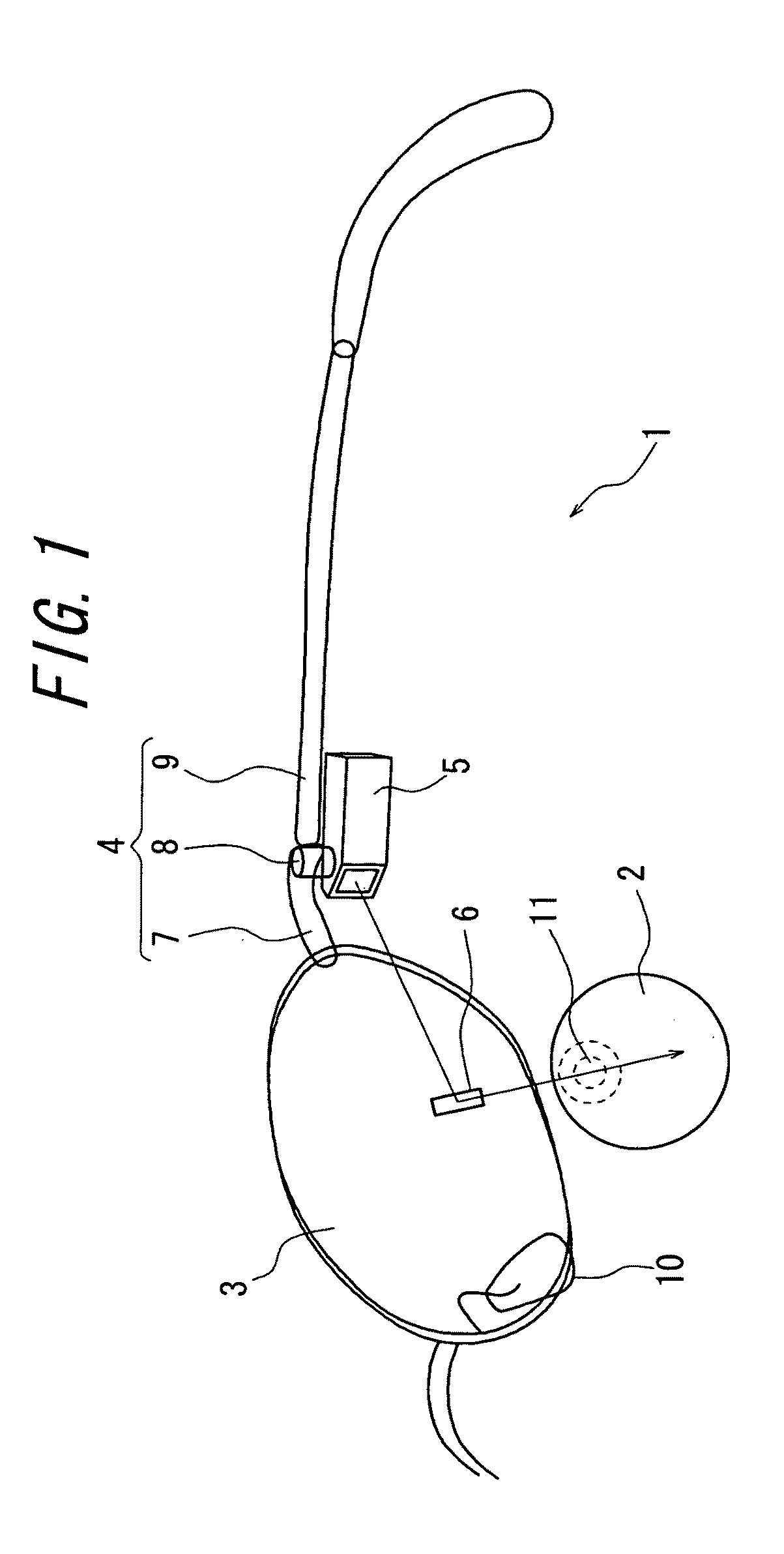
[0030]FIG. 1 is a partial configuration diagram schematically illustrating main parts of a spectacles-type image display device in accordance with a first embodiment of the present invention. In this diagram, an eyeball 2 of the right eye of a viewer when he / she wears the spectacles-type image display device 1 is also shown. The spectacles-type image display device 1 has a configuration in which an image output unit 5 and a plane mirror 6 constituting a reflection unit is added to a spectacle mainly constituted by a spectacle lens 3 and a spectacle frame 4.

[0031]The spectacle frame 4 includes an endpiece 7 that is fixed to the spectacle lens 3 or to a frame of the spectacle lens 3 and is located at both ends on the front surface of the spectacle and a temple 9 foldably coupled through the endpiece 7 and a hinge 8. The position of the spectacles-type image display device 1 is fixed with respect to the eyeball 2 of the viewer by hanging temples 9 over ears of the viewer and putting a ...

second embodiment

[0044]FIG. 7 is a diagram illustrating a configuration and in-use state of a spectacles-type image display device in accordance with a second embodiment of the present invention. FIG. 7 shows, in addition to a schematic configuration of the spectacles-type image display device 1, a light path of the image light that is output from the image output unit 5 and reaches the pupil 11 of the eyeball 2.

[0045]As shown in FIG. 7, the spectacles-type image display device in accordance with the present embodiment includes, in addition to the configuration of the spectacles-type image display device 1 of FIG. 1, a deviation prism 21 coupled to the temple 9 and a projection lens 22 coupled to the output surface of the deviation prism 21. The deviation prism 21 and the projection lens 22 may be integrally molded. Further, the device is configured so that the image light that is output from the image output unit 5 along the temple 9 is incident on the incident surface of the deviation prism 21, is...

third embodiment

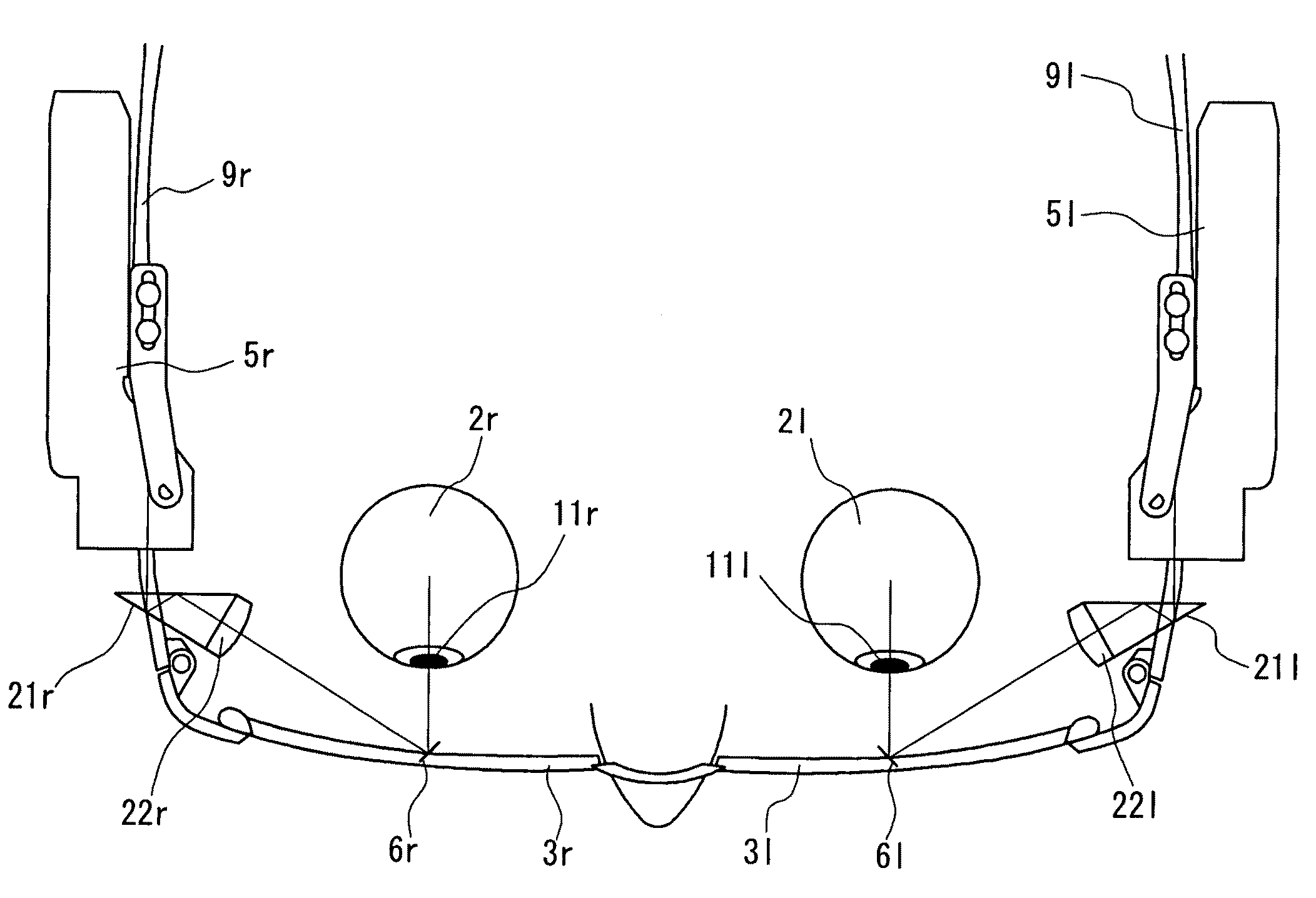
[0049]FIG. 9 is a diagram illustrating a configuration and in-use state of a spectacles-type image display device in accordance with a third embodiment of the present invention. In the present embodiment, image output units 5l and 5r, deviation prisms 21l and 21r, projection lenses 22l and 22r and plane mirrors 6l and 6r are respectively provided with respect to the left eyeball 2l and the right eyeball 2r. Except for the plane mirrors 6l and 6r provided respectively straight in front of each eyeball, each configuration of the spectacles-type image display device of FIG. 10 for the right eye is provided for the left eye.

[0050]In this case, in the sate where a viewer faces the front, electronic images output from the image output unit 5l on the left side and electronic images output from the image output unit 5r on the right side are superimposed and displayed in the field of view and in front of the viewer and, thereby in addition to the effects of the second embodiment, three-dimen...


PUM


Abstract

A spectacles-type image display device comprises an image output unit for outputting image light of images to be displayed and a reflection unit disposed in a field of view of at least one eyeball of a viewer. The reflection unit is adapted to reflect the image light output from the image output unit toward the eyeball of the viewer so that the viewer can see virtual images of the images. The minimum value of a width of a projection cross-section of the reflection unit in an output direction of the image light to the eyeball is smaller than a dark-adapted pupil diameter of human and is larger than a light-adapted pupil diameter of human.

Description

CROSS-REFERENCE TO RELATED APPLICATION[0001]The present application claims priority from Japanese Application No. 2009-209749 filed on Sep. 10, 2009, the content of which is incorporated herein by reference.FIELD OF THE INVENTION[0002]The present invention relates to spectacles-type image display devices.BACKGROUND OF THE INVENTION[0003]Conventionally, as a spectacles-type image display device, for example, a device that includes an image output unit held on the temple side of spectacles and an eyepiece optical unit held adjacent to a lens of spectacles is suggested. Such spectacles-type image display device is configured so that the image light of electronic images to be displayed that is output from the image output unit is incident on an eyeball of a viewer through an eyepiece optical unit so that the viewer can see the images. In such spectacles-type image display device, usually, the electronic images and the background images that transmit a spectacle lens are superimposed and...

Claims


Application Information

Patent Timeline
Patent Type & Authority Patents(United States)
IPC IPC(8): G09G5/00H04N13/04G02B27/14
CPCG02B27/0172G02B2027/0178G02B2027/0123G02B2027/0118
Inventor SUGIHARA, RYOHEITATSUTA, SEIJIIBA, YOICHI
Owner OLYMPUS CORP
Learn More