
Bone dilator

a bone dilator and bone cement technology, applied in the field of bone dilators, can solve the problems of spinal cord injury, paraplegia, and even paralysis, and achieve the effect of reducing the leakage rate of bone cemen

Active Publication Date: 2012-10-23
GUOYONG YIN
View PDF12 Cites 8 Cited by
  • Summary
  • Abstract
  • Description
  • Claims
  • Application Information

AI Technical Summary

Benefits of technology

The bone dilator effectively restores 91% of lost vertebral height, significantly reduces bone cement leakage, and is more cost-effective than existing methods, providing substantial kyphosis correction and pain relief.

Problems solved by technology

Compression fracture of vertebral body caused by osteoporosis is one of the serious complications.
Severe spine fractures may lead to injury of the spinal cord and even paraplegia.
The result is far from the claimed in the design.
Whereas at upper and lower end plates, where restoration to the height of the vertebral body is mostly needed, the inflation is suppressed due to greater resistance.(2) Leakage rate of the injected bone cement is still relatively high due to the limited restoration in the height of the vertebral body.(3) Although BK pertains to minimally invasive surgery, the cost of one balloon is very high.
This constitutes an enormous economic burden to senior patients suffering from osteoporotic compression fracture of vertebral body.
Moreover, since the balloon is easy to be pierced by the sharp bone chips during placement or inflation, the replacement of the balloon is needed, thus aggravating the economic burden on the patients.

Method used


Image

  • Bone dilator
  • Bone dilator
  • Bone dilator

Examples


Embodiment Construction

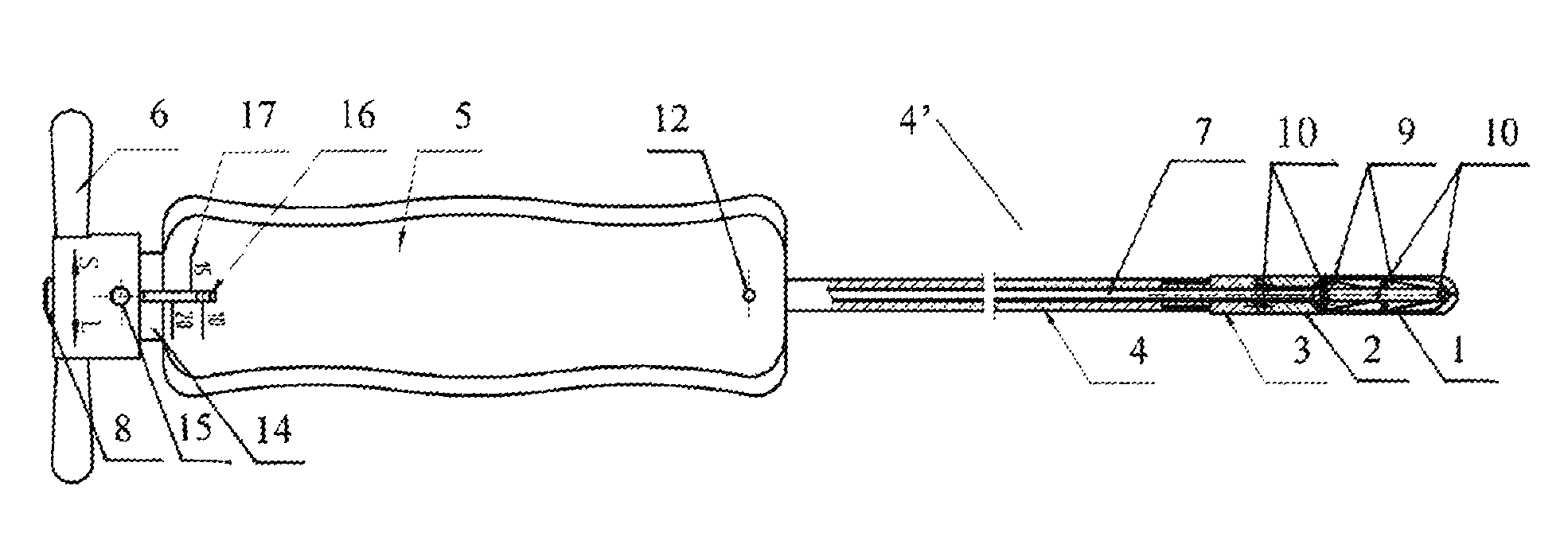
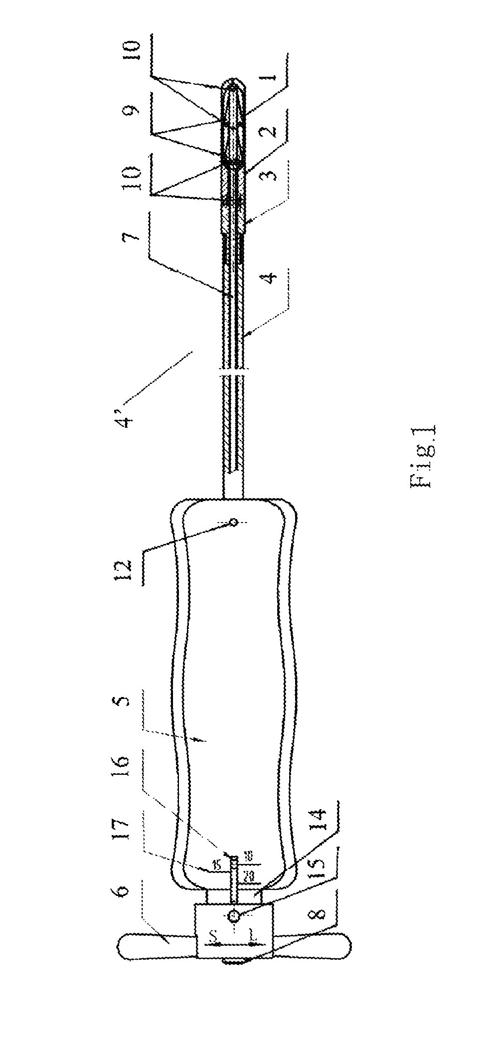
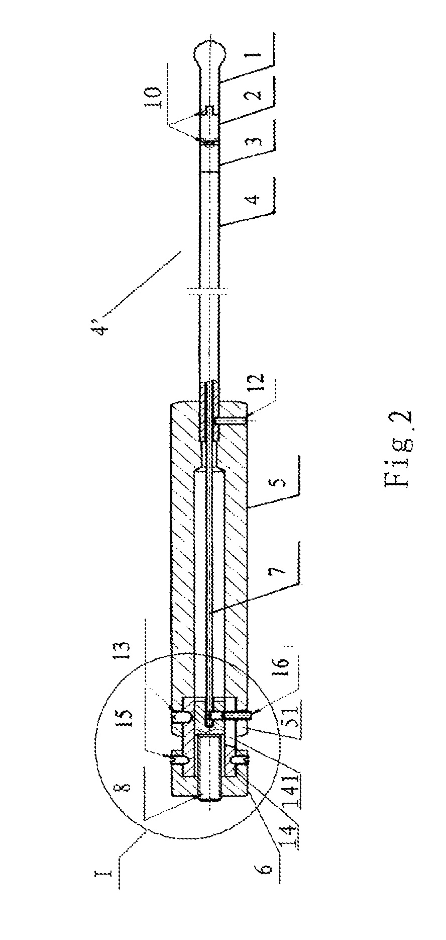
[0020]For illustration purpose, the right sides in FIGS. 1 and 2 are referred to as distal ends or fronts, and the left sides are referred to as proximal ends or rears.

[0021]In FIGS. 1-4, specific embodiments of the bone dilator according to the present invention are described in greater detail. The structure of the bone dilator according to the present invention comprises a head portion 1, a neck portion 2, a connecting tube 4′, a handle 5, and a rotary hilt 6. The head portion 1, the neck portion 2, the connecting tube 4′ and the handle 5 are all arranged as hollow bodies, through which a pull rod 7 penetrates. The head portion 1 and the neck portion 2 are integrated as a whole via hinged joint therebetween. At the center of the rotary hilt 6 is disposed a tension bolt 8, which is connected to a proximal end of the pull rod 7.

[0022]To make it easier for fabrication, the connecting tube 4′ can also consist of a connecting tube body 4 and a waist portion 3, and such a combination ha...


PUM


Abstract

The present invention relates to a bone dilator designed for treating compression fracture of vertebral body, and fractures of cancellous bones at other sites. The bone dilator comprises a head portion, a neck portion, a connecting tube, a handle and a rotary hilt. The head portion embodies different shapes for use at different locations. When the rotary hilt is rotated clockwise and the pull rod is pulled backwards, the upper and the lower parts of the head portion keep parallel or at a predetermined angle during expanding. When the rotary hilt is rotated counterclockwise and the pull rod is pushed forwards, the head portion and the neck portion completely join together, the distal end of the pull rod and the bar stays are completely or partially retracted in grooves inside the head portion and the neck portion.

Description

RELATED APPLICATIONS[0001]This is a continuation-in-part application of PCT Application No. PCT / CN2006 / 002441 filed on Sep. 19, 2006 which claims priority to Chinese Patent Application 200510094420.1 filed Sep. 19, 2005. Accordingly, this continuation-in-part application claims priority to PCT Application No. PCT / CN2006 / 002441 (Sep. 19, 2006) and to Chinese Patent Application 200510094420.1 (Sep. 19, 2005) (by way of PCT Application No. PCT / CN2006 / 002441). The disclosures of both PCT / CN2006 / 002441 and Chinese Patent Application 200510094420.1 are hereby incorporated by reference.FIELD OF THE INVENTION[0002]The present invention is related to a medical instrument for minimally invasive orthopedic operation, more particularly to a bone dilator, which is used mainly for treating osteoporotic compression fracture of vertebral body. This instrument can also be used for treating fractures of cancellous bones at other sites and certain traumatic or pathologic compression fracture of verteb...

Claims


Application Information

Patent Timeline
Patent Type & Authority Patents(United States)
IPC IPC(8): A61B17/00
CPCA61B17/0206A61B17/025A61B17/8858A61M29/02A61B2017/0256
Inventor WU
Owner GUOYONG YIN
Learn More