Child chair
a child chair and seat technology, applied in the field of child chairs, can solve the problems of inconvenient user calling for other functions, poor structural variety of the prior art child chairs, and inability to adapt to the needs of users,
- Summary
- Abstract
- Description
- Claims
- Application Information
AI Technical Summary
Benefits of technology
Problems solved by technology
Method used
Image

Examples
first embodiment
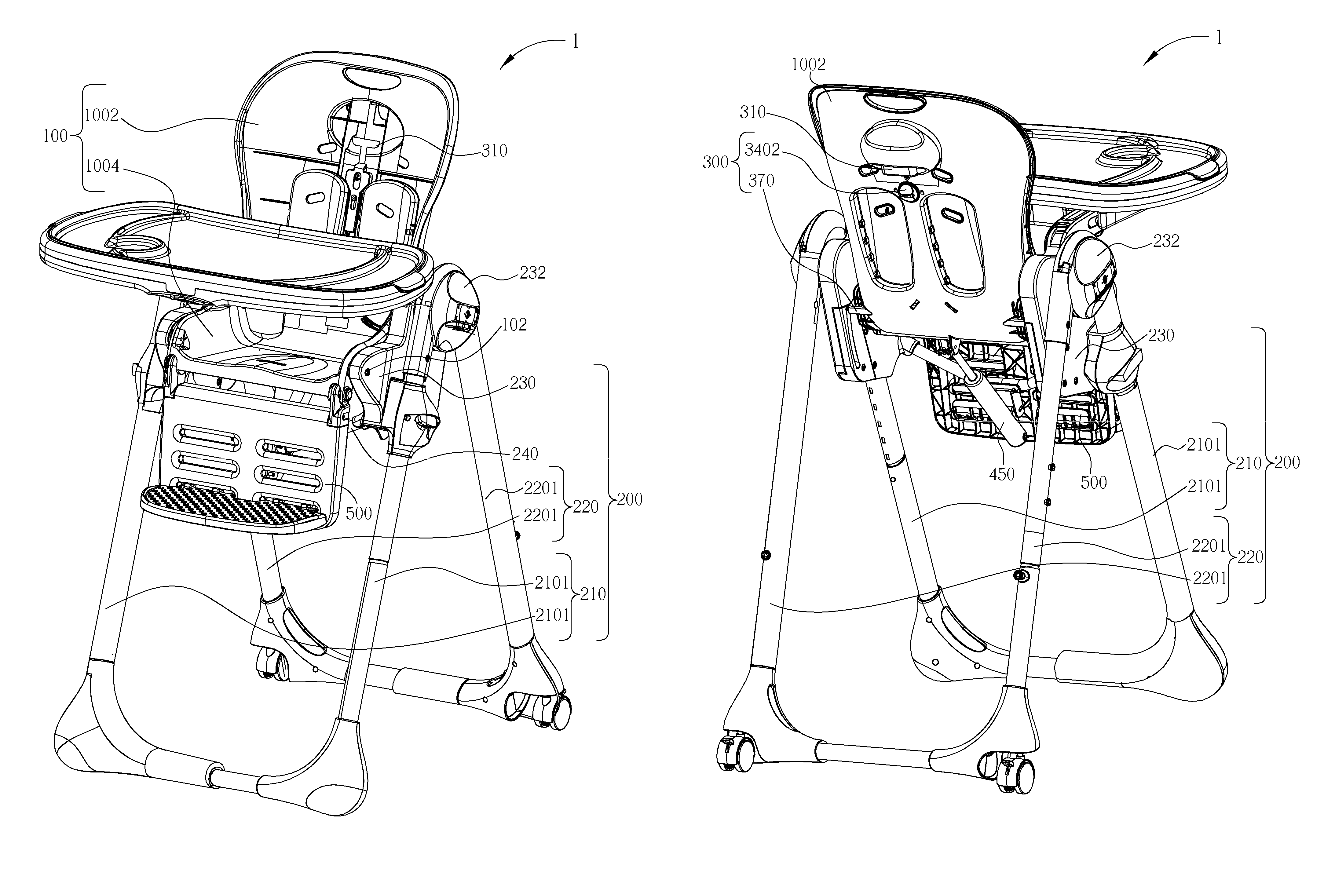
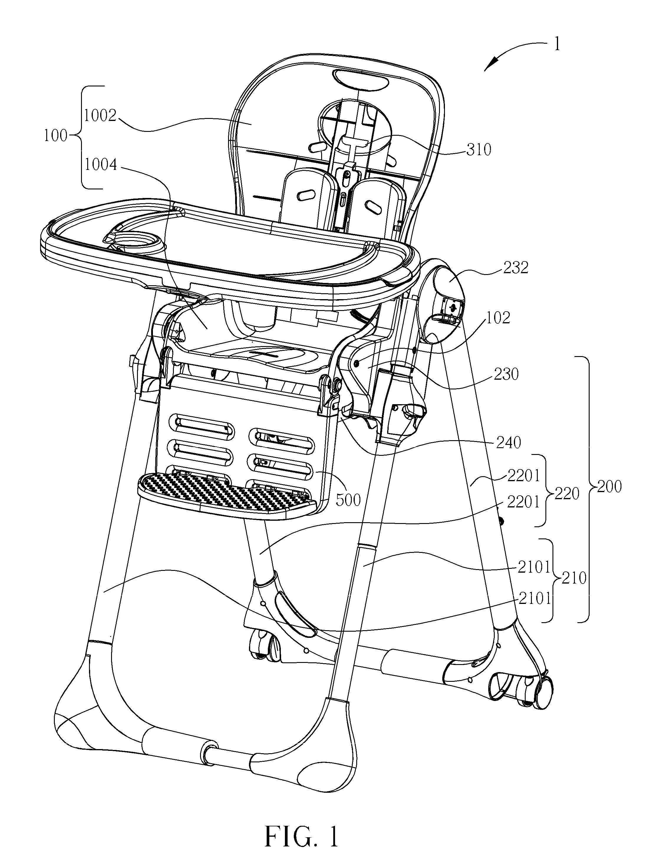
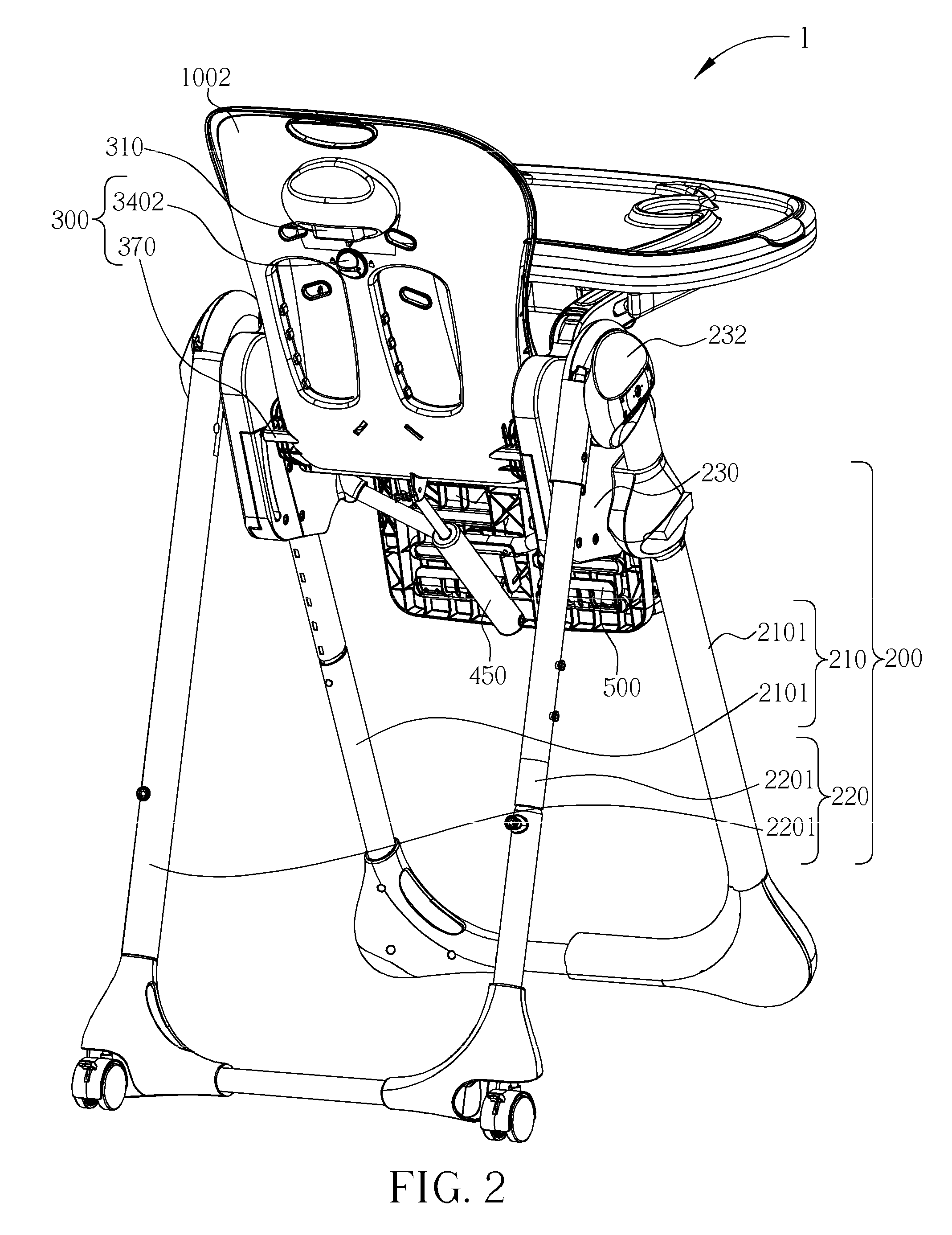
[0047]Please refer to FIG. 3 to FIG. 9 showing the reclining adjusting device. FIG. 3 is a diagram of the engaging device 350 and actuator 310 according to the present invention. FIG. 4 is a diagram of the locking device 3102 and the actuator 310 according to the present invention. FIG. 5 is a partial-enlarged diagram of the actuator 310 in the release status according to the present invention. FIG. 6 is a partial-enlarged diagram of the actuator 310 in the locking status according to the present invention. FIG. 7 is a diagram of the engaging device 350 according to the present invention. FIG. 8 is a partial-enlarged diagram of the engaging device 350 according to the present invention. FIG. 9 is a partial-enlarged diagram of the engaging device 350 and the frame 200 according to the present invention. Referring to FIG. 3 to FIG. 7, the seat 100 is pivoted with the frame 200 by the pivot axis 102. The actuator 310 is mounted on the seat 100, and includes a drag rod 3104 having an op...
second embodiment
[0056]Please refer to FIG. 15 to FIG. 17. FIG. 15 is a lateral view of the engaging device 360 according to the present invention. FIG. 16 is a diagram of the adjusting device 3604 according to the present invention. FIG. 17 is a diagram of the engaging device 360 and the reclining adjusting device 300 according to the present invention. The reclining adjusting device 300 includes the actuator 310 and an engaging device 360 which is connected to the actuator 310. The actuator 310 includes the drag rod 3104 and the elastic element 3110. The operating portion 3106 is formed at the top end of the drag rod 3104, and two flexible members 3105 is form on the bottom end of the drag rod 3104. The two flexible members 3105 are extended respectively to the two sides of the seat 100 by two stabilizing members 3107 on the seat 100 by the flexible members 3105. The end of each flexible member 3105 secured an adjusting pin 3608 that forms as the engaging device 360. The seat coupled 230 of the fr...
third embodiment
[0059]Please refer to FIG. 23 to FIG. 27. FIG. 23 is a posterior view of the locking device 3302 in the locking status according to the present invention. FIG. 24 is a perspective of the locking device 3302 in the locking status according to the present invention. FIG. 25 is a posterior view of the locking device 3302 in the release status according to the present invention. FIG. 26 is a perspective of the locking device 3302 in the release status according to the present invention. FIG. 27 is a partial-enlarged diagram of the locking device 3320 according to the present invention. The locking device 3302 is a button which slides transversely relative to a seat 100, and is mounted on the seat 100 in a piercing manner. The locking device 3302 includes an operating part 3307 and a retaining part 3308, wherein the operating part 3307 is mounted on the back side of the backrest 1002; the retaining part 3308 is mounted on the inner side of the backrest 1002 and is fixed with the operatin...
PUM
 Abstract
Description
Claims
Application Information
 - Generate Ideas
- Intellectual Property
- Life Sciences
- Materials
- Tech Scout
- Unparalleled Data Quality
- Higher Quality Content
- 60% Fewer Hallucinations
Browse by: Latest US Patents, China's latest patents, Technical Efficacy Thesaurus, Application Domain, Technology Topic, Popular Technical Reports.
© 2025 PatSnap. All rights reserved.Legal|Privacy policy|Modern Slavery Act Transparency Statement|Sitemap|About US| Contact US: help@patsnap.com