
Discharge device

a discharge device and discharge technology, applied in the direction of instruments, liquid handling, closures using stoppers, etc., can solve the problem of not being able to discharg

Active Publication Date: 2012-10-23
APTAR RADOLFZELL
View PDF11 Cites 2 Cited by
  • Summary
  • Abstract
  • Description
  • Claims
  • Application Information

AI Technical Summary

Benefits of technology

The invention provides a flexible and comfortable blocking device with a low manufacturing cost. The blocking device has a ratchet and a blocking handle that can move in different directions. A thrust member connects the blocking handle to the ratchet and can transfer force in different directions. The ratchet can be moved by the blocking handle in the same direction as the actuation handle. The blocking handle can be moved manually and the ratchet can be pushed in the same direction as the actuation handle. The ratchet can be connected to the blocking handle through a thrust member, which changes its alignment during movement. The blocking device can be compact and can be easily guided. The ratchet and blocking handle can be fixed in guides or grooves in the housing. The invention provides a reliable and flexible blocking device that offers improved user experience and cost-effectiveness.

Problems solved by technology

It is further known to provide a blocking device for discharge devices which only enables actuation in a released operating mode, whilst in a blocked operating mode no discharge is possible.

Method used


Image

  • Discharge device
  • Discharge device
  • Discharge device

Examples


Embodiment Construction

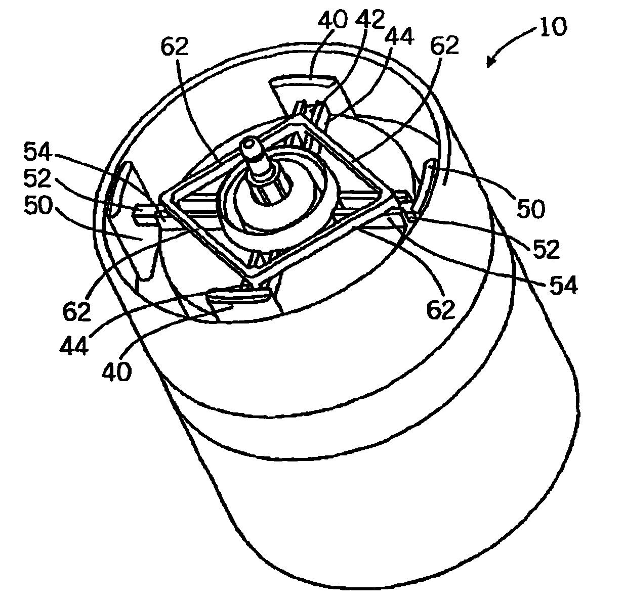
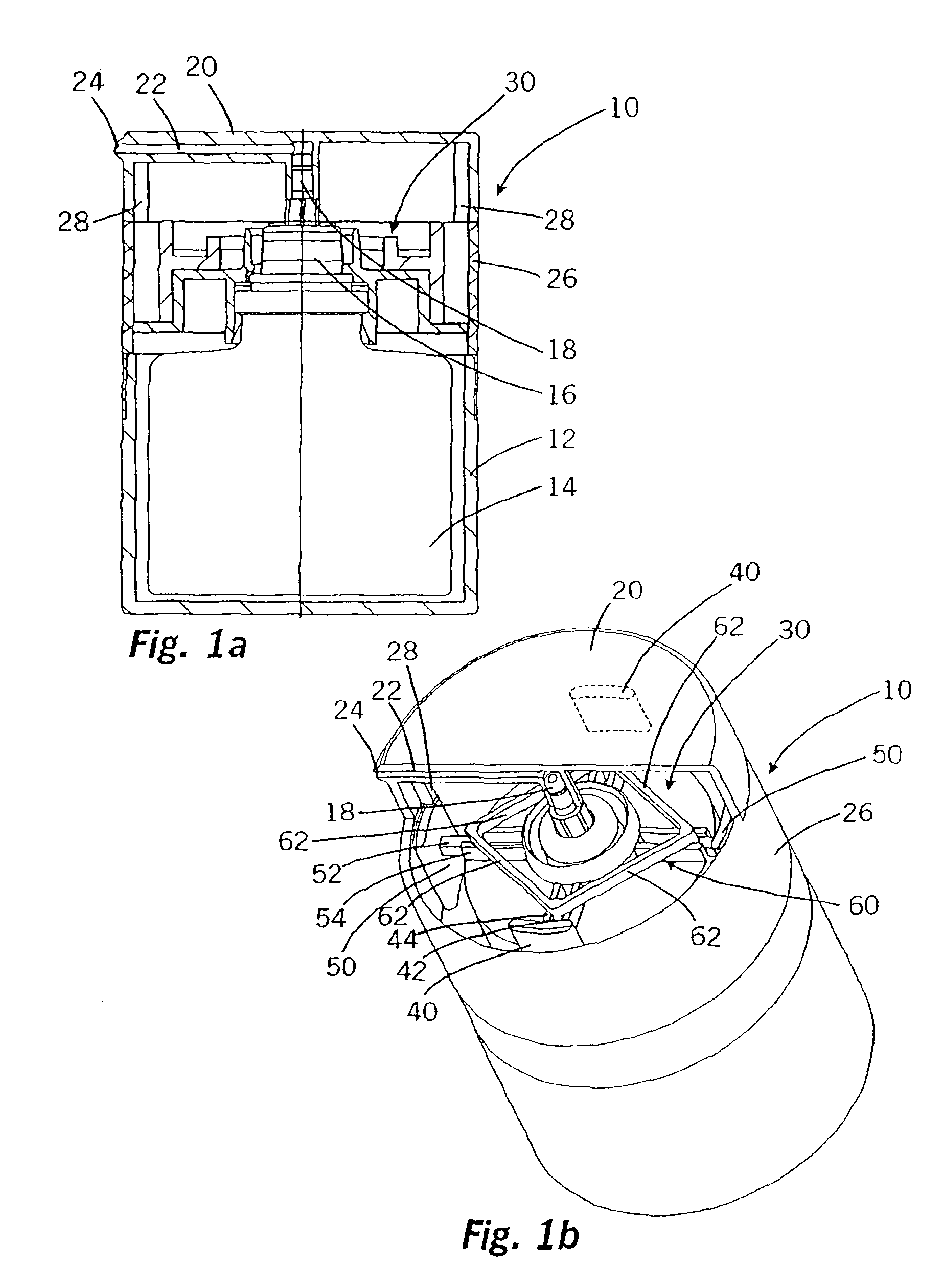
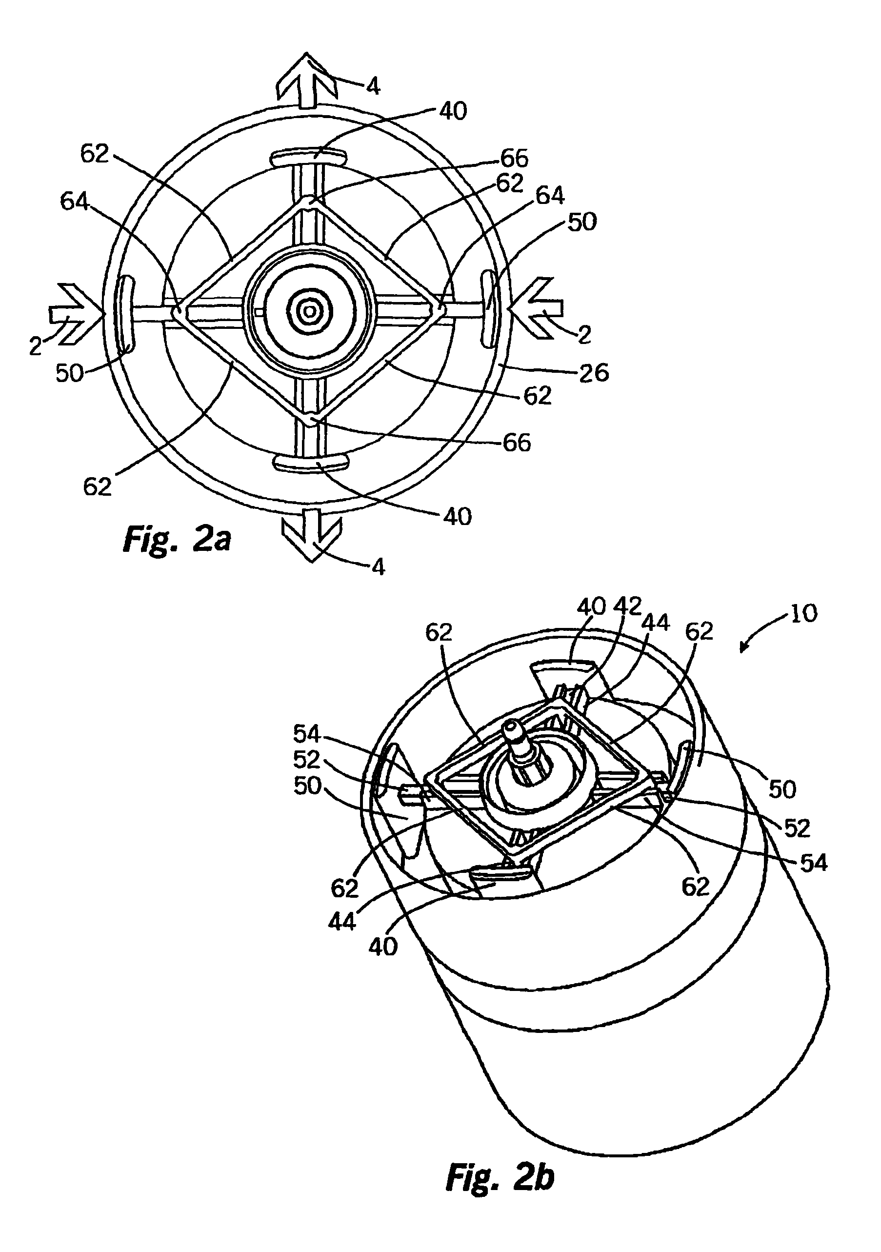
[0025]FIGS. 1a and 1b show the structure of the discharge device.

[0026]The discharge device 10 has a housing 12 into which a pump dispenser 14 with a pump device 16 is inserted. The pump device 16 is arranged such that it can be actuated by pressing down on a nozzle 18 and in response medium is transferred from a reservoir of the pump dispenser 14 outwards through the nozzle 18. An actuation handle 20 is provided on the nozzle 18 and embraces a discharge channel 22 through which medium is channeled to a discharge opening 24 after exiting from the nozzle 18. A flexible annular wall 26 is provided between the housing 12 and the actuation handle 20, the lower end of which is secured to the housing 12, and the upper end of which is secured to the actuation handle 20. This annular wall 26 protects a blocking device 30 which is arranged between the housing 12 and the actuation handle 20.

[0027]This blocking device 30 is particularly recognisable in FIG. 1b. The blocking device 30 has two b...


PUM


Abstract

A discharge device for a housing, an actuation handle, a transport device for transporting a liquid medium through a discharge opening, and a blocking device to restrict movement of the handle relative to the housing.The blocking device comprises at least one ratchet that can be moved wherein it does not hinder the movement of the actuation handle wherein it restricts the movement of the actuation handle relative to the housing, at least one blocking handle movable in response to application of force, and at least one thrust member through which the blocking handle is operably coupled to the ratchet, whereby the thrust member is connected to the blocking handle and to the ratchet such that the application of force enables the ratchet to be moved.

Description

FIELD OF THE INVENTION[0001]The invention relates to a discharge device for preferentially liquid media with a housing, an actuation handle that can move relative to the housing and with a transport device which is designed, in response to the movement of the actuation handle relative to the housing, to transport medium outwards through a discharge opening. A blocking device is provided through which the movement of the actuation handle relative to the housing can be restricted.BACKGROUND OF THE INVENTION[0002]Discharge devices for media, especially for liquid media, have been known for some time for both pharmaceutical and cosmetic purposes. The discharge devices are generally conceived so that they are provided directly with a reservoir for the medium, from which the medium is then discharged when the actuation handle is displaced manually, for instance pressed downwards.[0003]It is further known to provide a blocking device for discharge devices which only enables actuation in a ...

Claims


Application Information

Patent Timeline
Patent Type & Authority Patents(United States)
IPC IPC(8): G01F11/00B67B1/08
CPCB05B11/3059B05B11/1059
Inventor GUENTHER, CHRISTIANE
Owner APTAR RADOLFZELL
Learn More