Eureka AIR delivers breakthrough ideas for toughest innovation challenges, trusted by R&D personnel around the world.

Method and device for estimating properties of a telecommunication transmission line

a technology properties, applied in the field of transmission line analysis, can solve the problems of low accuracy, inability to work for long lines, and methods for estimating properties of telecommunication transmission lines, and achieve the effect of long lines and acceptable strength of received signals

Active Publication Date: 2012-10-16
TELEFON AB LM ERICSSON (PUBL)
View PDF8 Cites 0 Cited by
  • Summary
  • Abstract
  • Description
  • Claims
  • Application Information

AI Technical Summary

Benefits of technology

[0023]It is thus an advantage of the present invention that the method can be used through the normal signal paths (e.g. speech paths in the case of a POTS board) of a line board for normal operation of a transmission line, and thus no metallic test access is needed.
[0024]A further advantage is that it can use the POTS band and can be used through a POTS line board.
[0025]An advantage of using a POTS board is that such boards are usually present in telecommunication exchanges.
[0026]Another advantage is that if the POTS band is used for measurement (whether through a POTS board or not), it can be carried out without disrupting ongoing DSL traffic.
[0027]A further, important advantage is that properties may be estimated for longer lines than previously possible from comparison between a sent and a received resulting signal measured through a line board.
[0028]Still an advantage of using the POTS band (i.e. relatively low frequencies)) is that signal attenuation in a transmission line is generally lower for lower frequencies. A low attenuation means that an acceptable strength of the received signal can be achieved for longer lines, that is, longer lines can be measured.

Problems solved by technology

Current methods for estimating properties for telecommunication transmission lines suffer from the drawbacks that they require dedicated hardware or metallic test access, or have low accuracy, or do not work for long lines.

Method used


Image

  • Method and device for estimating properties of a telecommunication transmission line
  • Method and device for estimating properties of a telecommunication transmission line
  • Method and device for estimating properties of a telecommunication transmission line

Examples


Embodiment Construction

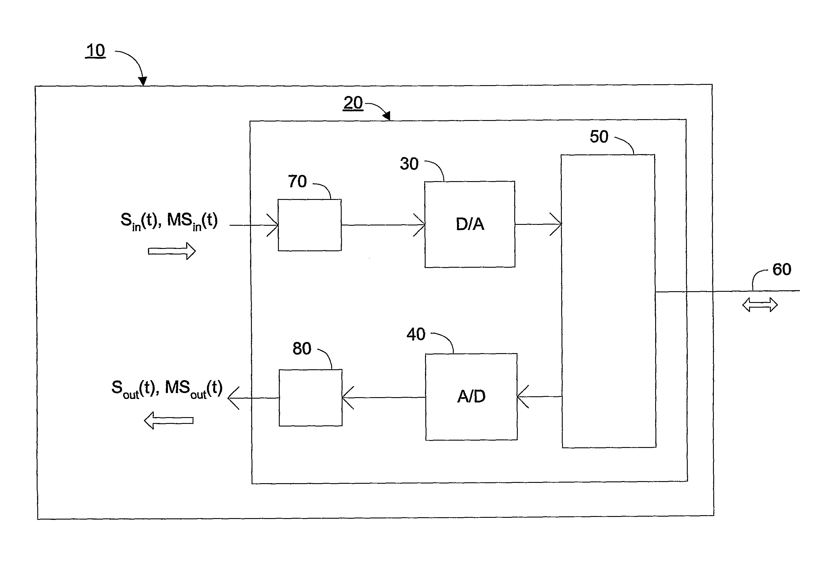
[0039]With reference to FIG. 1, telecommunication transmission lines 60 typically terminate in one end at a customer premises site 61 and in the other end at a central office setting 130. Here, the lines are typically connected to line boards 100. The line boards 100 are typically controlled by a processor 110 of a telecommunication exchange. It is of great interest to be able to measure properties of the lines 60 from the central office setting 130.

[0040]The initial steps of the present method are to send a signal on a transmission line 60 and receive a resulting signal. From the relationship between the signals, a complex line input impedance can then be calculated for each of a number of frequencies present in the signals. From that impedance, other transmission properties of the line may be determined.

[0041]Here will be described how to practice the method when the signals are sent and received through a line board 100 and when the line board is a POTS line board.

[0042]Somewhat ...


PUM


Abstract

A method and device for estimating one or more transmission properties of a telecommunication transmission line. At least one signal is sent on the line, the at least one signal including at least two frequencies for which the absolute value of the line propagation constant times the line length is less than π, and a resulting signal is received. An estimate of at least one transmission line property is then determined by examining the relationship between the sent and resulting signal or signals. The process may be repeated, if necessary. The estimate determination may also be repeated one or more times, with each successive estimate preferably using for the determination only those frequencies for which, as previously estimated, the absolute value of the line propagation constant times the line length is less than π.

Description

TECHNICAL FIELD OF THE INVENTION[0001]The present invention relates to the field of transmission line analysis.DESCRIPTION OF RELATED ART[0002]It is of great interest for the operation of telecommunication networks to measure the properties of the transmission lines of the network. The results of such measurements can be used for e.g. detecting faults, locating faults, predicting certain faults which are about to occur, and estimating the suitability and capacity of a line for certain services, such as DSL.[0003]A variety of methods and devices can be used to estimate line properties.[0004]Single-ended line test, SELT is an important way of testing. Here, line properties are estimated from measurements made at one end of the line only.[0005]One class of SELT equipment is dedicated measurement equipment with metallic test access. Here, a special-purpose measurement device is galvanically connected to the transmission line when the measurement is made.[0006]Such measurements can be ma...

Claims


Application Information

Patent Timeline
Patent Type & Authority Patents(United States)
IPC IPC(8): H04M1/24H04M3/08H04M3/22
CPCH04B3/46
Inventor ALLEVAD, STEFANODLING, PERFERTNER, ANTONIBACK, HENRIKLINDQVIST, FREDRIKBORJESSON, PER OLARIUS I RIU, JAUME
Owner TELEFON AB LM ERICSSON (PUBL)
Why Eureka
Eureka Blog
Learn More