
Membrane bioreactor

a bioreactor and membrane technology, applied in the field of membrane bioreactors, can solve the problems of reducing the operating capacity of the bioreactor, affecting the quality of the bioreactor, and requiring a large portion of the bioreactor to be taken off-line for maintenance,

Inactive Publication Date: 2012-10-16
NICK JUERGEN T +2
View PDF8 Cites 51 Cited by
  • Summary
  • Abstract
  • Description
  • Claims
  • Application Information

AI Technical Summary

Benefits of technology

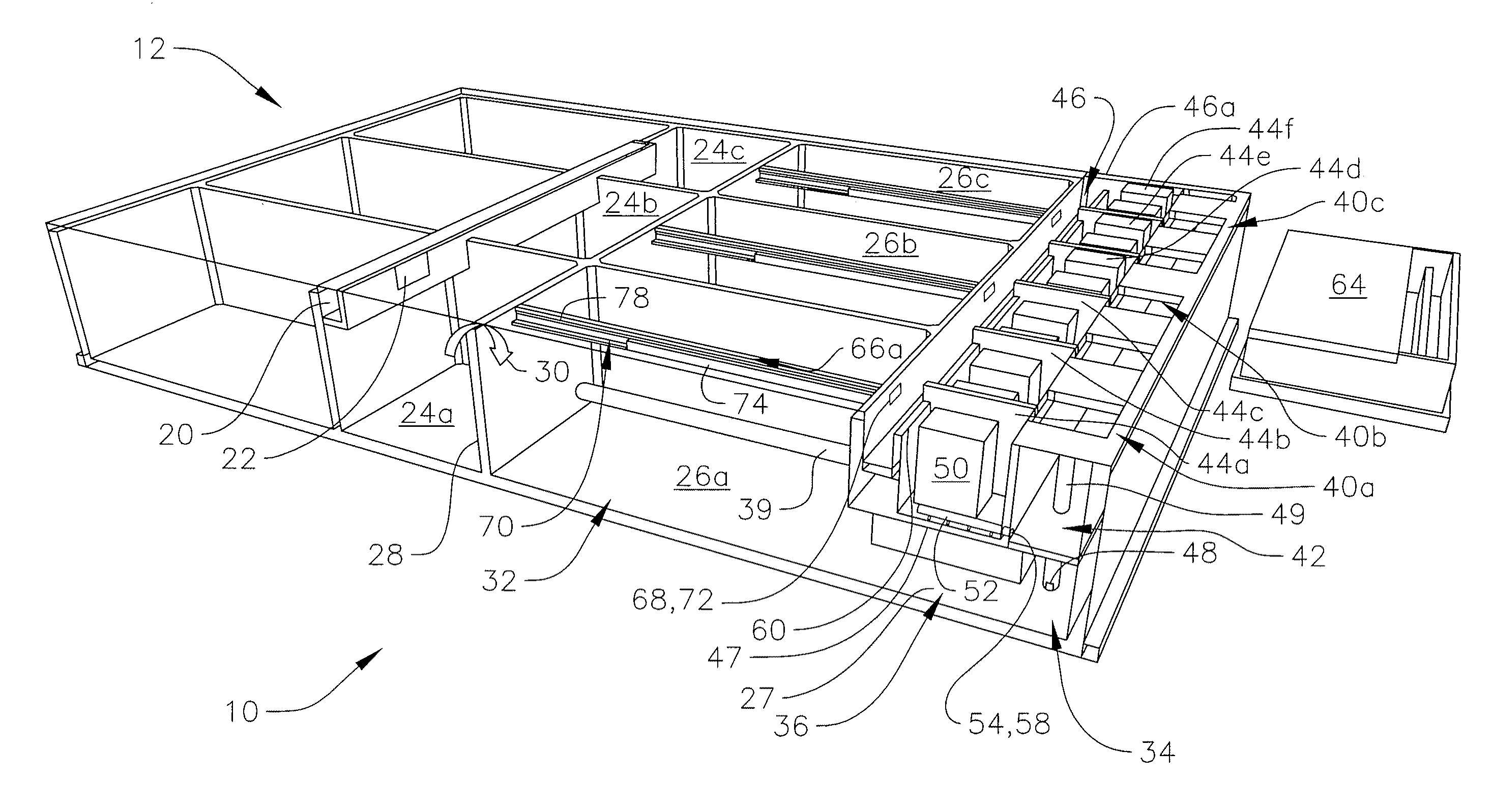
"The present invention is about an improved membrane bioreactor for wastewater treatment. The invention includes first and second anoxic basins for anoxic treatment of wastewater, and first and second aerobic basins for aerobic treatment of wastewater. The first and second aerobic basins are connected in series with the first and second anoxic basins, and a membrane chamber is connected to the aerobic basins. The membrane chamber has multiple membrane tanks arranged in parallel with each other. The membrane bioreactor also includes a common wall shared by the anoxic and aerobic basins, as well as fluid flow paths for the wastewater to flow from the anoxic basins to the aerobic basins. The membrane bioreactor has improved treatment efficiency and can handle a larger amount of wastewater compared to conventional membrane bioreactors."

Problems solved by technology

First, the water is biologically treated in an aerobic process by micro-organisms that consume the organic contaminants in the water and produce solid waste sludge.
While membrane bioreactors provide an effective method for treating wastewater, they have some drawbacks.
Many bioreactor designs contain several tanks and basins through which the wastewater flows in series, and as a result repair and maintenance of an individual tank requires a large portion of the bioreactor to be taken off-line.
This can significantly reduce the operating capacity of the bioreactor.
These piping systems can be expensive to install and maintain.

Method used


Image

  • Membrane bioreactor
  • Membrane bioreactor
  • Membrane bioreactor

Examples


Embodiment Construction

[0033]The present invention relates to wastewater treatment facilities, and more particularly to an improved membrane bioreactor for treatment of wastewater. The membrane bioreactor passes wastewater through an anoxic basin, an aerobic basin, and a membrane chamber and recycles the water through these basins several times to thoroughly treat the water. The water is biologically treated in the anoxic and aerobic basins and then is filtered through membranes in the membrane chamber, as described more fully below. In one embodiment, the improved membrane bioreactor has a modular design that incorporates common fill channels and effluent channels to enable individual tanks to be taken off-line for repair or maintenance without disrupting the operation of other tanks up- or downstream. The modular design enables up- or downstream tanks to continue operating at full capacity even when one of the tanks in series requires maintenance or repair. Additionally, in one embodiment, the improved ...


PUM

PropertyMeasurementUnit
heightaaaaaaaaaa
heightaaaaaaaaaa
diameteraaaaaaaaaa

Abstract

The present invention relates to wastewater treatment facilities, and more particularly to an improved membrane bioreactor for treatment of wastewater. In one embodiment, a membrane bioreactor for treatment of wastewater includes first and second anoxic basins for anoxic treatment of such wastewater, and first and second aerobic basins for aerobic treatment of such wastewater. The bioreactor also includes a first flow path connecting the first anoxic basin and the first aerobic basin, and a second flow path connecting the second anoxic basin and the second aerobic basin, for flow of the wastewater from the respective anoxic basin into the respective aerobic basin. The bioreactor also includes a membrane chamber with a plurality of membrane tanks, the membrane chamber being arranged in series with the aerobic basins, and the membrane tanks being arranged in parallel with each other, and third and fourth flow paths connecting the membrane chamber to the first and second aerobic basins. The membrane chamber may extend into the aerobic basin.

Description

CROSS-REFERENCE TO RELATED APPLICATIONS[0001]This application claims priority to and the benefit of U.S. Provisional Patent Application No. 61 / 093,226, filed on Aug. 29, 2008 and U.S. Provisional Patent Application No. 61 / 092,653, filed on Aug. 28, 2008, the contents of both of which are incorporated herein by reference.FIELD OF THE INVENTION[0002]The present invention relates to wastewater treatment facilities, and more particularly to an improved design of a membrane bioreactor for treatment of wastewater.BACKGROUND[0003]Membrane bioreactors are one of several types of Activated Sludge Process wastewater treatment facilities designed to remove contaminants from domestic and runoff wastewater. This wastewater comes from residences, businesses, industry, and runoff water from rainfall or flooding. Wastewater treatment facilities remove organic and solid waste from water so that the water can be recycled back into the environment. A facility should be able to accommodate dry and wet ...

Claims


Application Information

Patent Timeline
Patent Type & Authority Patents(United States)
IPC IPC(8): C02F3/30
CPCC02F3/1273C02F3/30Y02W10/10Y02W10/37
Inventor NICK, JUERGEN T.PERSLOW, JOHAN A.MATTHEWS, JR., JAMES A.
Owner NICK JUERGEN T
Learn More