
Utility monitoring system with variable logging

a monitoring system and variable technology, applied in the field of utility monitoring systems, can solve the problems of over-all higher total cost of ownership, and achieve the effect of maximizing the resources of the power monitoring system

Active Publication Date: 2012-10-02
SQUARE D CO
View PDF1 Cites 9 Cited by
  • Summary
  • Abstract
  • Description
  • Claims
  • Application Information

AI Technical Summary

Benefits of technology

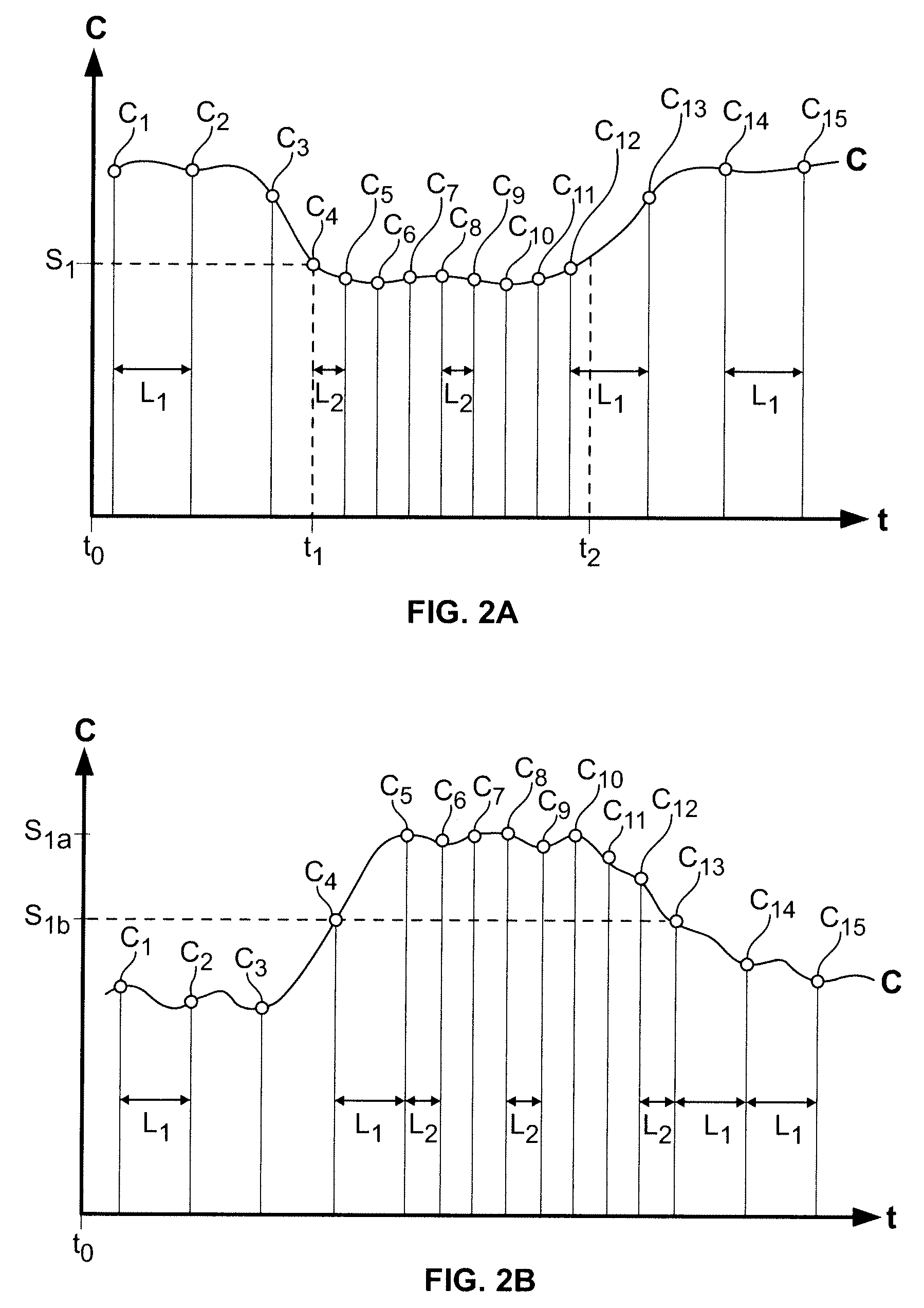
[0004]The present invention provides a solution that allows a utility monitoring system to store a sufficient amount of data during events of interest. The data is transmitted from a plurality of IEDs to a server utilizing a minimum or reduced amount of bandwidth prior to having to overwrite the data in the IEDs. The present invention provides methods for varying a logging interval of monitored characteristic values. The varied logging intervals allow IEDs to monitor a characteristic or parameter and store a sufficient amount of monitored characteristic values and / or associated information for later use in analyzing the monitored characteristic during normal operation or during an event of interest. The varied logging intervals increase based on a satisfaction of a condition to maximize the power monitoring system's resources such that monitored characteristic values being logged with an increased frequency (i.e., shorter logging interval) is during events of interest and that monitored characteristic values being logged during normal operation or non-events of interest is logged with a decreased frequency (i.e., longer logging interval).

Problems solved by technology

Managing data generated in the IEDs presents data management issues, such as data storage within the IEDs and bandwidth for transmitting data from the IEDs to the computer.
Power monitoring systems that require IEDs with larger storage capacity and networks with larger bandwidth cost more to setup and maintain, which results in an overall higher total cost of ownership.

Method used


Image

  • Utility monitoring system with variable logging
  • Utility monitoring system with variable logging
  • Utility monitoring system with variable logging

Examples


Embodiment Construction

[0018]Although the invention will be described in connection with certain aspects and / or embodiments, it will be understood that the invention is not limited to those particular aspects and / or embodiments. On the contrary, the invention is intended to cover all alternatives, modifications, and equivalent arrangements as may be included within the spirit and scope of the invention as defined by the appended claims.

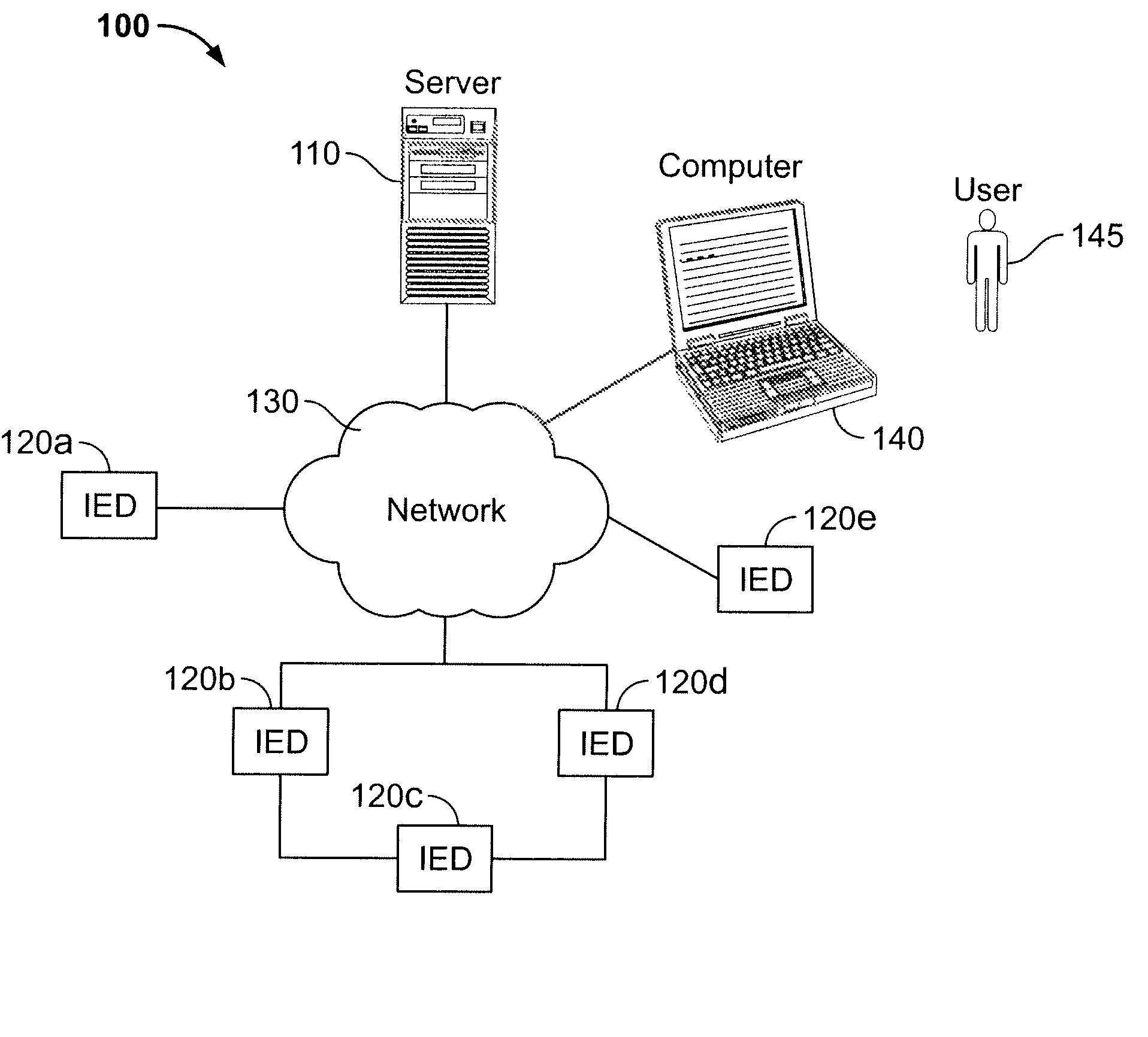
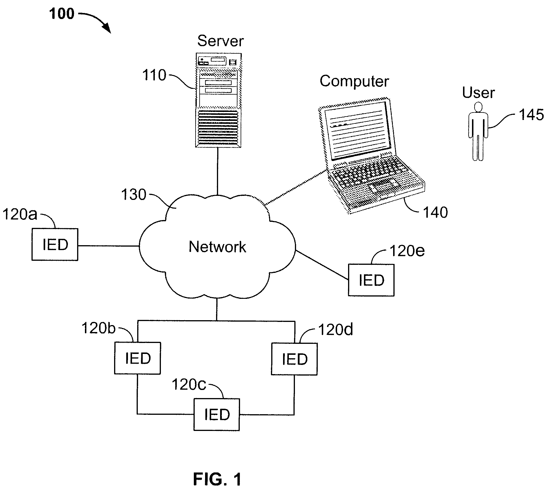
[0019]Referring to FIG. 1, a utility monitoring system 100 is generally shown. The utility monitoring system 100 includes a server 110, a plurality of intelligent electronic devices 120a-e (hereafter “IEDs”), a network 130, and a computer 140. The IEDs 120a-e are communicatively coupled through the network 130 to the server 110 and the computer 140. As used herein, an IED refers to any system element or apparatus with the ability to sample, collect, or measure one or more operational characteristics or parameters of a utility system. The utility system being monitored by th...


PUM


Abstract

A method of storing data in a utility monitoring system includes monitoring a characteristic of a utility system in an intelligent electronic device (IED) to produce monitored characteristic values that are buffered in the IED. The IED is communicatively coupled to a server via a network. The monitored characteristic values are indicative of the characteristic. The method further includes storing a first monitored characteristic value of the buffered monitored characteristic values periodically at a first logging interval in a memory of the IED. The method further includes storing a second monitored characteristic value of the buffered monitored characteristic values periodically at a second logging interval in the memory of the IED in response to satisfying a criterion. The second logging interval is distinct from the first logging interval.

Description

FIELD OF THE INVENTION[0001]The present invention relates generally to utility monitoring systems and in particular, to utility monitoring systems with variable logging intervals.BACKGROUND OF THE INVENTION[0002]Utility systems, such as an electrical utility system, are monitored by a network of intelligent electronic devices (“IEDs”) coupled to a computer and / or server for monitoring various parameters or characteristics of the electrical utility system. The network of IEDs and the computer are typically referred to collectively as a power monitoring system. The power monitoring systems can include between one to several thousand networked IEDs communicatively coupled to the computer. Managing data generated in the IEDs presents data management issues, such as data storage within the IEDs and bandwidth for transmitting data from the IEDs to the computer. Depending on the frequency that data is logged by each of the networked IEDs, the demands on resources of the power monitoring sy...

Claims


Application Information

Patent Timeline
Patent Type & Authority Patents(United States)
IPC IPC(8): G01R21/00G01R11/56
CPCG01R19/2513
Inventor VAN GORP, JOHN C.GASPER, MARCUSRAFFO, STEVEN B.
Owner SQUARE D CO
Learn More