
Aggregator, monitor, and manager of distributed demand response

a demand response and aggregator technology, applied in the direction of instruments, computer control, process and machine control, etc., can solve the problems of demand response implementation on a reactive basis, demand response capacity management on an individual basis, and the collection and integration of data from these applications and systems is extremely difficult outside of the intended operation

Active Publication Date: 2012-09-04
MCG VERSIFY ACQUISITION LLC
View PDF48 Cites 126 Cited by
  • Summary
  • Abstract
  • Description
  • Claims
  • Application Information

AI Technical Summary

Benefits of technology

This system enables utilities to maximize power grid performance by treating demand response resources as aggregated assets, improving energy management and enabling real-time control and reporting, thus enhancing overall system performance and reducing peak demand.

Problems solved by technology

However, one disadvantage of existing demand response systems is that the demand response is implemented on a reactive basis.
Another disadvantage of existing demand response systems is that each demand response capacity is managed on an individual basis.
However, these applications are typically not built with integration in mind with each application being too proprietary in nature and specifically tailored for a particular power generation operation.
Accordingly, collection and integration of data from these applications and systems are extremely difficult outside of the intended operation.
Another difficulty with prior art systems is the disparate number of locations even within the organization that need access to the data.
The traditional siloed applications are typically client-server based applications and it is difficult to provide access to everyone in need of the data.
In addition, due to the generally isolated nature of the prior art systems as described above, combining qualitative event type data (e.g., real-time or recorded plant operations data) and quantitative data (e.g., Supervisory Control and Data Acquisition (SCADA) and market data) becomes difficult and cumbersome, if not impossible, due to the size and disparity of the data.
This task becomes even more complicated when disparate data sources with varying data formats are used.

Method used


Image

  • Aggregator, monitor, and manager of distributed demand response
  • Aggregator, monitor, and manager of distributed demand response
  • Aggregator, monitor, and manager of distributed demand response

Examples


Embodiment Construction

General Description

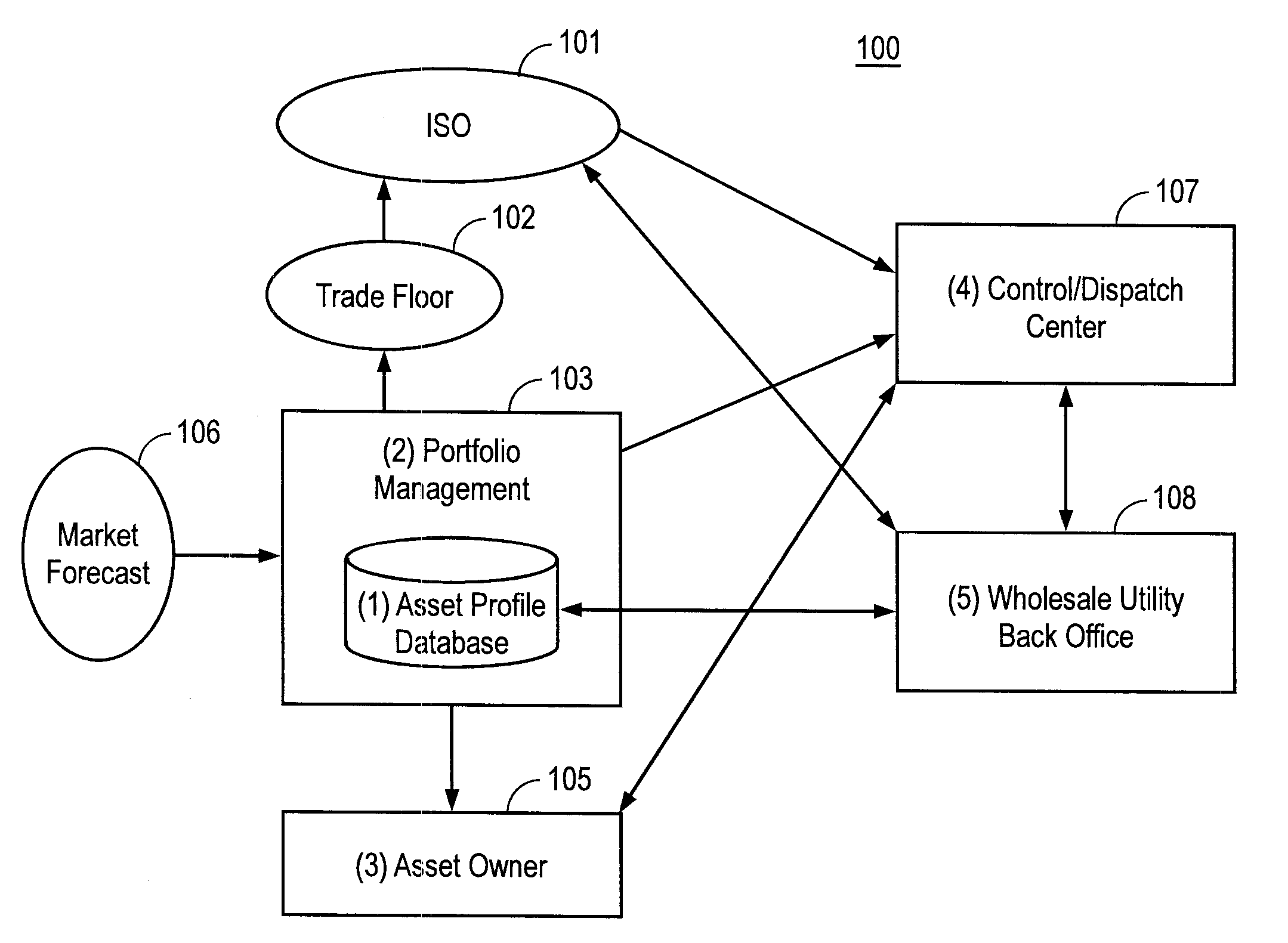
[0041]The invention generally encompasses systems including:

[0042]a database to store demand response data, the demand response data including demand response agreement parameters, demand response load and energy demand characteristics of one or more demand response customers, the demand response load characteristics including power consumption capacity of each of one or more demand response loads; an aggregator to aggregate the demand response loads based on the demand response data and forecast data into a demand response portfolio;

[0043]a monitor to monitor power demand of one or more demand response customers and one or more power grids; and

[0044]a dispatcher to notify the one or more demand response customers of the demand response portfolio and to notify a utility of a response from the one or more demand response customers whether to control the demand response load to return the power consumption capacity of the demand response load back to the one or more...


PUM


Abstract

The invention broadly encompasses a system including a database to store demand response data, the demand response data including demand response agreement parameters, demand response load and energy demand characteristics of one or more demand response customers, the demand response load characteristics including power consumption capacity of each of one or more demand response loads, an aggregator to aggregate the demand response loads based on the demand response data and forecast data into a demand response portfolio, a monitor to monitor power demand of one or more demand response customers and one or more power grids, and a dispatcher to notify the one or more demand response customers of the demand response portfolio and to notify a utility of a response from the one or more demand response customers whether to control the demand response load to return the power consumption capacity of the demand response load back to the one or more power grids.

Description

[0001]This application claims the benefit of U.S. provisional patent application No. 61 / 075,742, which was filed on Jun. 25, 2008 and is incorporated herein by reference in its entirety.I. FIELD OF THE INVENTION[0002]The present invention relates to a system facilitating the utilization of distributed demand response capacities, and more particularly to a distributed demand response aggregator, monitor, and manager. The present invention also relates to a performance monitor and reporter for distributed demand response, and more particularly to a performance monitor and reporter for distributed demand response that is adaptable to handle data from any data source.II. DISCUSSION OF THE RELATED ART[0003]As demand for energy continues to rise, it becomes increasingly important to find alternative sources of energy. While one solution is to create new sources of energy to add to the current energy capacity, another solution is to forego the use of energy (i.e., conservation) to return t...

Claims


Application Information

Patent Timeline
Patent Type & Authority Patents(United States)
IPC IPC(8): G05D3/12G05D9/00G05D5/00G05D11/00G05D17/00
CPCH02J3/14G06Q50/06G05F1/66G05B15/02Y02B70/3225Y04S20/222H02J2003/003Y04S10/54H02J3/008Y04S50/10Y04S10/58Y04S50/00Y04S50/14Y02P90/82Y04S50/16G06Q10/06315G06Q30/0206H02J3/003H02J2310/58H02J3/144Y04S20/00Y02B90/20Y04S10/50
Inventor IPPOLITO, DAVIDCONA, PETER
Owner MCG VERSIFY ACQUISITION LLC
Learn More