High-capacity device for receiving mailpieces

a high-capacity, mailpiece technology, applied in the field of mail handling, can solve the problems of increasing the feed and storage capacity, affecting the quality of mailpieces, and requiring an increase in the area used for such storage, so as to reduce the speed of ejection of mailpieces

Active Publication Date: 2012-09-04
NEOPOST TECH SA
View PDF21 Cites 4 Cited by
  • Summary
  • Abstract
  • Description
  • Claims
  • Application Information

AI Technical Summary

Benefits of technology

[0007]Thus, by holding the stack vertical throughout the storage process, it is possible to accumulate a larger number of mailpieces with a device of the same length.
[0013]The device of the invention may also further comprise a flexible flap mounted at the inlet of the device over the entire width of said conveyor belt for the purpose of reducing the speed of ejection of the mailpieces.

Problems solved by technology

However, this increase in the feed and storage capacity must not be achieved to the detriment of the amount of space that needs to be dedicated to the franking machine or “postage meter”.
Although this problem can be solved simply for feed devices in which the mailpieces are disposed in a vertical stack and in which an increase in the height of the stack does not give rise to any change in the footprint of the module, i.e. the floor area it occupies, it is much more difficult to solve for storage devices (or stackers) in which such mailpieces are, in conventional manner, stored horizontally, and in which an increase in the quantity of mailpieces stored in this way requires an increase in the area used for such storage.
Unfortunately, that storage-by-accumulation solution is not fully satisfactory because, although it operates properly for the first mailpieces, it does not operate properly after a certain number of mailpieces because, while the conveyor belt continues to push the bottom portion of the stack against the sloping surface, the top portion is no longer affected by that thrust.
As a result, the stack becomes trapezoidal with a small width at its base and a large width at its top that eventually causes the stack to fall onto the conveyor belt, thereby causing the device to jam.
Unfortunately, in addition to its particular complexity due to the motor-drive of the rollers, that device also suffers from the drawback of requiring a very large footprint.

Method used


Image

  • High-capacity device for receiving mailpieces
  • High-capacity device for receiving mailpieces

Examples


Embodiment Construction

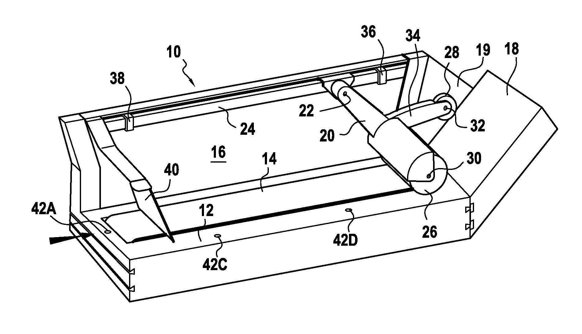
[0018]FIG. 1 shows a storage device 10 that, in conventional manner, includes a rectangular mailpiece-receiving deck 12 through which a conveyor belt 14 passes that extends over the entire length of the deck along and in the immediate vicinity of a longitudinal referencing wall 16, the end of the deck that is opposite from its end at the inlet of the device being formed by a sloping surface 18. Continuity between the longitudinal wall and the sloping surface is provided by a link plate 19.

[0019]In accordance with the invention, this device also includes a pivot arm 20 on which a friction roller 26 and a holding roller 28 are mounted, which pivot arm is mounted to move both vertically about a hinge pin 22 fastened in a manner such that it extends perpendicularly to the referencing wall, and also horizontally along a slide rail 24 fastened to the referencing wall. In order to enable the device to be used in all of the feed and accumulation configurations, the sloping surface 18 and th...


PUM

PropertyMeasurementUnit
angleaaaaaaaaaa
widthaaaaaaaaaa
speedaaaaaaaaaa

Abstract

A storage device for a mail-handling machine, said storage device comprising a mailpiece-receiving deck along a longitudinal edge of which a referencing wall extends, and through which a conveyor belt passes for the purpose of conveying mailpieces along said referencing wall from an inlet of the device towards a sloping surface against which said mailpieces accumulate, said storage device further comprising a pivot arm that is mounted to move both vertically about hinge pin and horizontally along a slide rail, on which arm firstly a friction roller is mounted for pressing said mailpieces against the conveyor belt, and secondly a holding roller is mounted for pressing said mailpieces against the sloping surface.

Description

FIELD OF THE INVENTION[0001]The present invention relates to the field of mail-handling and it relates more particularly to a storage device for a mail-handling machine.PRIOR ART[0002]Current mail-handling machines are increasingly fast, and such high franking rates require their feed and storage capacities to be increased in order to avoid the operator constantly needing to load and unload the machine. However, this increase in the feed and storage capacity must not be achieved to the detriment of the amount of space that needs to be dedicated to the franking machine or “postage meter”.[0003]Although this problem can be solved simply for feed devices in which the mailpieces are disposed in a vertical stack and in which an increase in the height of the stack does not give rise to any change in the footprint of the module, i.e. the floor area it occupies, it is much more difficult to solve for storage devices (or stackers) in which such mailpieces are, in conventional manner, stored ...

Claims


Application Information

Patent Timeline
Patent Type & Authority Patents(United States)
IPC IPC(8): B65H31/06
CPCB65H29/18B65H31/02B65H2301/42144B65H2404/152B65H2701/1916
Inventor DESIRE, REGIS
Owner NEOPOST TECH SA
Why Eureka
Try Eureka