
Aircraft engine thrust reverser

a thrust reverser and aircraft engine technology, applied in the field of thrust reverser structure, can solve the problems of increasing weight, reducing the service life of the articulating activating linkage, increasing the cost, etc., and achieves the effects of reducing the deployment stroke, and saving weigh

Active Publication Date: 2012-09-04
SHORT BROTHERS
View PDF14 Cites 17 Cited by
  • Summary
  • Abstract
  • Description
  • Claims
  • Application Information

AI Technical Summary

Benefits of technology

The present invention provides a power unit with a thrust reversing structure that can provide reverse thrust to a gas turbine engine. The power unit includes an efflux duct that directs gas fluid efflux in a first direction for propulsive thrust and can be redirected in a second direction for reverse thrust. The thrust reversing structure includes translating cowl portions that move from a stowed position to a deployed position to block the efflux duct and create the reverse thrust. The cowl portions move along a path that is inclined to the power unit axis. The invention optimizes the aerodynamic performance of the engine in its normal propulsive mode, reducing fuel burn and improving efficiency. The fixed structure and slider rails on which the cowl portions move can be positioned at different angles depending on the engine configuration. The invention also provides alternative aerodynamic devices such as slots and slats to secure the desired reverse thrust.

Problems solved by technology

Furthermore, the articulated activating linkage also adds weight, is prone to wear and requires maintenance all of which add cost.
However, in order to make this type of thrust reverser operate, the by-pass fan duct must have a more pronounced curvature or profile resulting in the surface area of the by-pass fan duct being increased which causes a small weight increase but, more importantly, causes pressure losses in the fan duct that may reduce forward thrust performance and consequently increase fuel burn.

Method used


Image

  • Aircraft engine thrust reverser
  • Aircraft engine thrust reverser
  • Aircraft engine thrust reverser

Examples


first embodiment

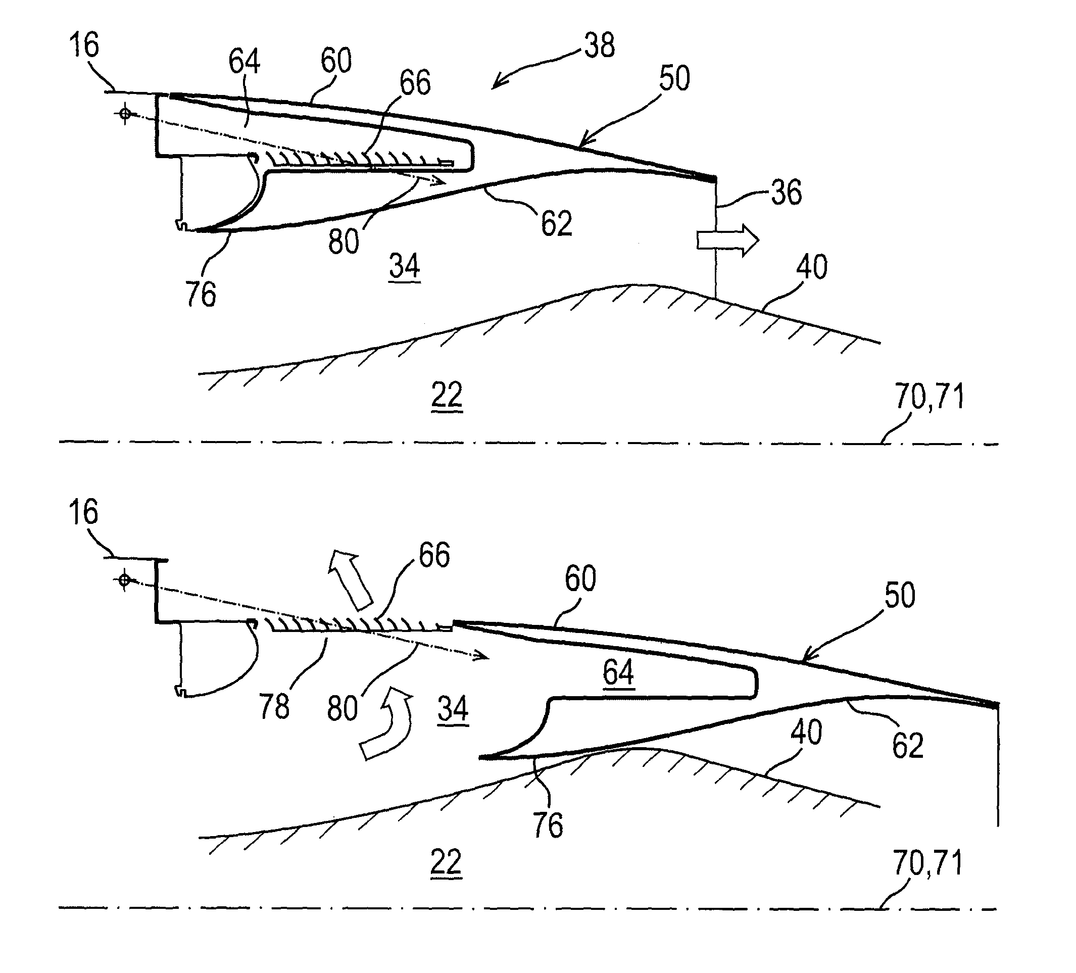
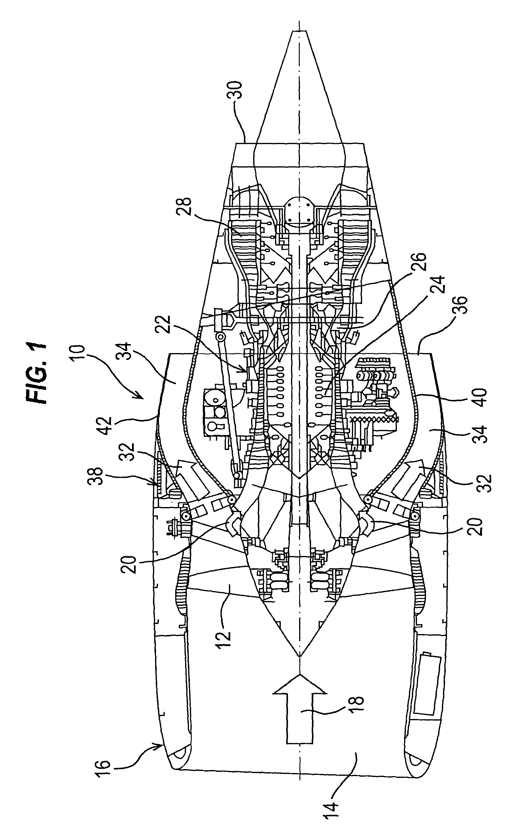
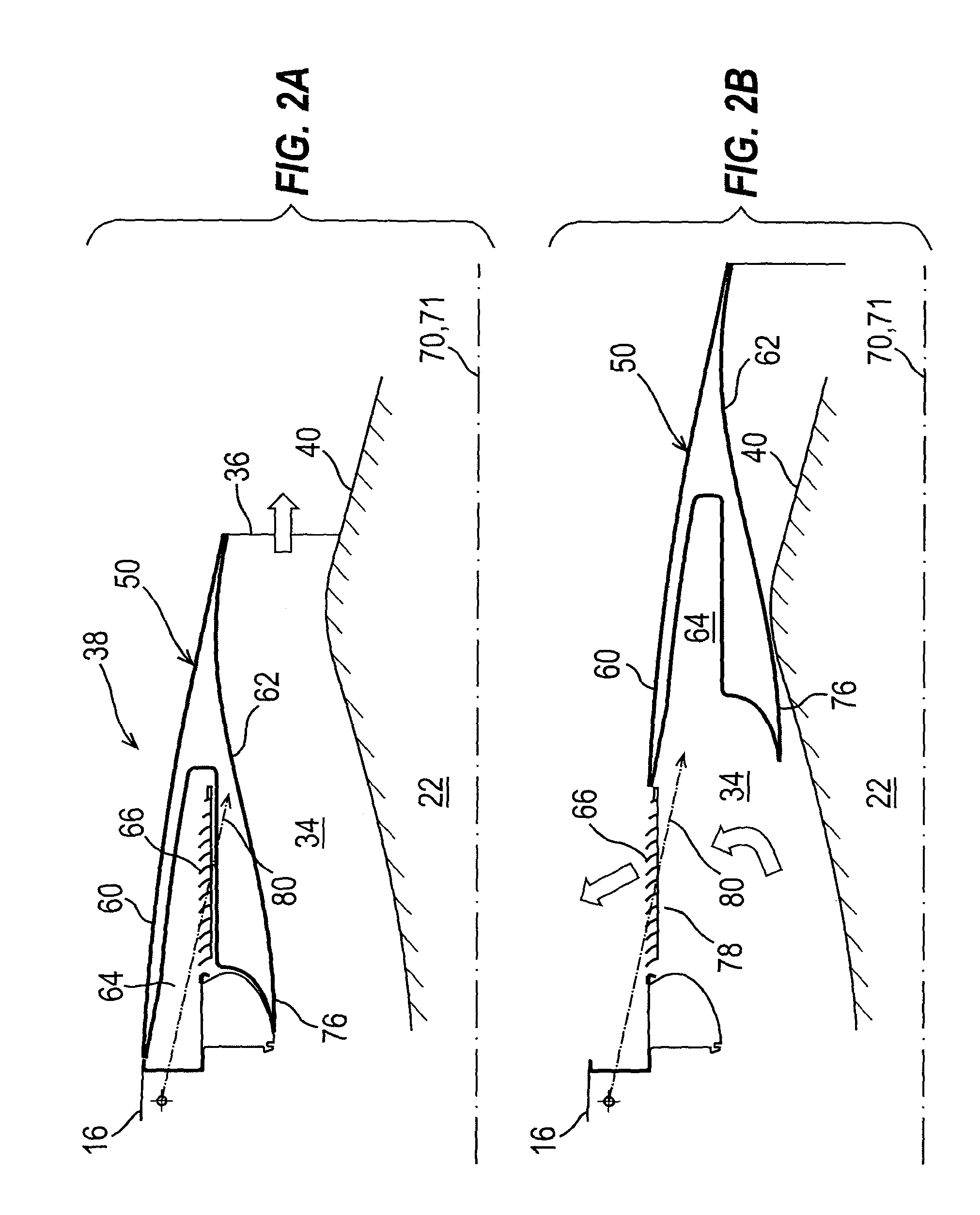
[0031]FIGS. 2A and 2B show a schematic cross section through a thrust reverser arrangement 38 according to the present invention; FIG. 2A being in the stowed (i.e. inoperative position) and 2B being in the deployed (i.e. operative position). Only the essential features of the invention are shown for the sake of clarity, and furthermore, only one side of the engine at a position circumferentially intermediate the location of slider rails on which the translating cowl portions (both of which to be described below) are mounted. FIGS. 2A and 2B are perhaps best viewed together with FIGS. 3A, 3B and FIG. 4 which show the thrust reverser arrangement of the present invention in the context of a whole engine 10 and a mounting pylon therefor.

[0032]The thrust reverser arrangement of the present invention comprises an inner by-pass fan duct cowling 40 surrounding the engine core 22 and an outer, translatable by-pass fan duct cowling portion 50. There is a matching by-pass fan duct cowling port...

third embodiment

[0037]the present invention is shown with reference to FIGS. 6A and 6B; 6A showing the thrust reverser arrangement in the stowed position and 6B in the deployed position. The basic structure of the reverse thrust arrangement in this embodiment is essentially the same as that described with reference to FIG. 2. However, in this embodiment, the reverse air flow assisting cascades 66 are replaced by a slot 100 arrangement defined by slats 102. The shape of the cavity 64 is so formed as to generate suitable flow and back pressure characteristics to assist air flow out of the second gaseous fluid exit opening 78, the slats 102 assisting the air flow to adhere to a nose portion 106 of the fixed cowl 16 to prevent flow separation and maximise reverse thrust air flow 108. The principles relating to control of air flow in this embodiment are fully described in EP-A-1 515 035 of common ownership herewith.

[0038]A fourth embodiment of the present invention is shown with reference to FIG. 7. In ...


PUM


Abstract

A power unit for providing propulsive thrust includes an efflux duct defining a first fluid flow path along which gaseous fluid travels for discharge from a first fluid exit opening to provide propulsive thrust. The power unit also has a thrust reversing structure which, when in a deployed position, redirects the flow of gaseous fluid along a second fluid flow path to discharge from a second fluid exit opening to provide reverse thrust. The thrust reversing structure includes longitudinally translating cowl portions, which are moveable from a stowed position to the deployed position where the translating cowl portions block a major portion of the first fluid exit opening to cause gaseous fluid to efflux from the second fluid exit opening. The translating cowl portions move in a generally longitudinal direction towards the deployed position along a path which is inclined to the power unit axis.

Description

CROSS-REFERENCE TO RELATED APPLICATION(S)[0001]This United States Non-Provisional Patent Application is a National Stage Entry based upon and relying for priority upon PCT Patent Application No. PCT / GB2007 / 003192, which was filed on Aug. 21, 2007. This patent application also relies for priority on Great Britain patent Application No. 0616740.7, which was filed on Aug. 24, 2006. The contents of both applications are incorporated herein by reference.FIELD OF THE INVENTION[0002]The present invention relates to a thrust reverser structure for an aircraft engine and to an engine having that thrust reverser structure.BACKGROUND[0003]Thrust reversers for aircraft engines, particularly gas turbine engines, are well known and take many and varied forms.[0004]One form of thrust reverser structure when used on a gas turbine engine having a by-pass fan and by-pass fan duct utilises so-called blocker doors which are activated by a cowl portion which translates rearwardly in a direction parallel...

Claims


Application Information

Patent Timeline
Patent Type & Authority Patents(United States)
IPC IPC(8): F02K3/02F02K1/72
CPCF02K1/72F05D2250/314Y02T50/671Y02T50/60
Inventor HATRICK, MICHAEL JOHN
Owner SHORT BROTHERS
Learn More